


8–19
62-11640
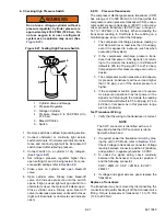
c. Leak Checking With Low Side Pumped Down
The low side of the system must be leak checked once
it is closed and all repairs complete.
1. Ensure the unit will not start automatically by
disabling any two way communication and plac-
ing the STOP/RUN-OFF switch in the OFF posi-
tion. Disconnect the high voltage source and
lockout/tagout the receptacle.
WARNING
!
Only a refrigerant cylinder containing
R404A should be connected to this refrig-
eration unit in order to pressurize the sys-
tem. However, dry nitrogen may be used to
increase pressure. Any other gas or vapor
will contaminate the system and require
additional removal and evacuation.
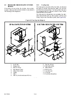
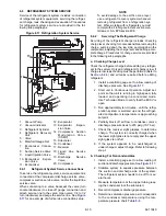
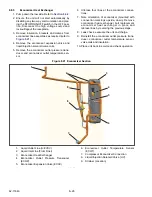
2. Connect refrigerant system equipment if not
already connected. Refer to
NOTICE
Do not vapor charge R404A. Only liquid
charging through the liquid line service
valve is acceptable.
3. Ensure that the operator message panel dis-
plays “RECOVER/LEAK CHK/EVAC MODE”
during the pressurizing and leak checking pro-
cedures. (Refer to
.) If the control
system switches to Charge Mode during the
process, switch it back to the “RECOVER/LEAK
CHK/EVAC MODE”.
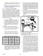
4. Pressurize the low side of the system 5 to 10
psig (0.3 to 0.7 bar) with refrigerant from the
high side by turning the liquid line service valve
off frontseat for a few seconds and then return-
ing to frontseat.
WARNING
!
Do not use a nitrogen cylinder without a
pressure regulator. Cylinder pressure is
approximately 2350 psig (159.9 bar). Do
not use oxygen in or near a refrigerant
system as an explosion may occur. (See
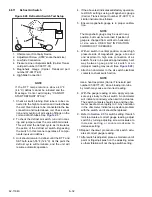
5. Connect a cylinder of dry nitrogen. Use the nitro-
gen to increase the low side pressure 20 to 150
psig (1.4 to 10.2 bar) to detect the leak. The
larger the leak the less pressure is required. The
smaller the leak, the greater the pressure
required.
6. The recommended procedure for finding leaks
from a system is with an electronic leak detector.
Checking joints with soapsuds is satisfactory
only for locating large leaks, or pinpointing small
leaks once a general area has been located.
7. Once leak checking is complete, remove the
refrigerant/ nitrogen vapor from the low side of
the system.
8. If no leaks are found the low side of the system
is ready for evacuation. (Skip to Step 11)
9. If any leaks are found they must be repaired
before proceeding.
10. Repeat steps 4 - 9 as necessary.
11. Disconnect the nitrogen cylinder. Evacuate the
low side of the system after all leaks are
repaired. (Refer to
.)
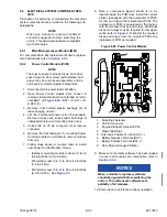
d. Leak Checking Compressor
The compressor connections, suction, discharge, and
economizer, must be leak checked once the compres-
sor is closed and all repairs complete.
1. Ensure the unit will not start automatically by
disabling any two way communication and plac-
ing the STOP/RUN-OFF switch in the OFF posi-
tion. Disconnect the high voltage source and
lockout/tagout the receptacle.
2. Connect refrigerant system service equipment
to the suction and discharge service valves, if
not already connected. Refer to
.
WARNING
!
Only a refrigerant cylinder containing
R404A should be connected to this refrig-
eration unit in order to pressurize the
system. However, dry nitrogen may be
used to increase pressure. Any other gas
or vapor will contaminate the system and
require additional removal and evacua-
tion.
NOTICE
Do not vapor charge R404A. Only liquid
charging through the liquid line service
valve is acceptable.
3. Pressurize the compressor 5 to 10 psig (0.3 to
0.7 bar) by opening the suction service valve for
a few seconds, then closing (frontseating) it
again.
Summary of Contents for Vector 8500
Page 23: ...62 11640 1 6 1 3 SAFETY DECALS ...
Page 24: ...1 7 62 11640 62 03958 ...
Page 25: ...62 11640 1 8 ...
Page 26: ...1 9 62 11640 ...
Page 27: ...62 11640 1 10 ...
Page 125: ...62 11640 SECTION 6 MESSAGECENTER PARAGRAPH NUMBER Page 6 1 MESSAGECENTER MESSAGES 6 1 ...
Page 321: ......
Page 322: ......


