Chapter 2
18
HDMA-4000 Part Names
HDMA-4000 Part Names
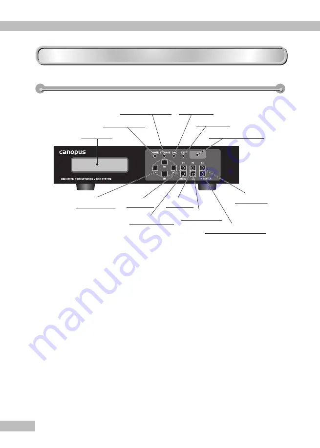
HDMA-4000/HDMA-4000Sync Front Panel
HDMA-4000/HDMA-4000Sync Front Panel
(1) LCD
(2) POWER LED
(3) STORAGE LED
(4) LINK LED
(5) KEY LED
(6) Infrared receiver
(7) Select Key
(8) F1 Key
(9) F2 Key
(10) F3 Key
(11) MENU Key
(12) STOP Key
(13) PLAY/ENTER Key
(1) LCD ...............................Displays the current operation status and setting
menus.
(2) POWER LED
.................Lights when HDMA-4000/HDMA-4000Sync operates.
- Unlit ........... Power is not on.
- Lit ............... Operating
- Blinking ...... Starting up/Shutting down
(3) STORAGE LED .............Lights up when the internal HDD is being accessed.
(4) LINK LED ......................Lights when HDMA-4000 and/or HDMA-4000Sync
is connected to a network (via a hub or other such
device).
- Unlit ........... Not connected to a network device
(Switching Hub, etc.)
- Lit ............... Connected to a network device, but
not sending/receiving data.
- Blinking ...... Connected to a network device, and
sending/receiving data.
(5) KEY LED .......................Lights when receiving a key signal from an infrared
remote controller or an external remote terminal.
(6) Infrared receiver ...........Built in infrared receiver for remote controllers.
Summary of Contents for HDMA-4000
Page 1: ...HDMA 4000 User Guide Engineered by Canopus Co Ltd...
Page 16: ...Chapter 1 16...
Page 32: ...Chapter 3 32 6 Click X Uninstallation is completed...
Page 51: ...HDMA 4000 Contents update Contents update Reference 1 Reference 1...
Page 71: ...HDMA 4000 Serial control Serial control Reference 3 Reference 3...
Page 88: ...Reference 3 88...
Page 124: ...Reference 4 124...
Page 130: ...Reference 5 130...
Page 131: ...HDMA 4000 Appendix Appendix...

