2
2
2-13
2-13
Technology > Stack Tray Unit > Stack Tray Operation
Technology > Stack Tray Unit > Stack Tray Operation
Stack Tray Unit
Stack Tray Operation
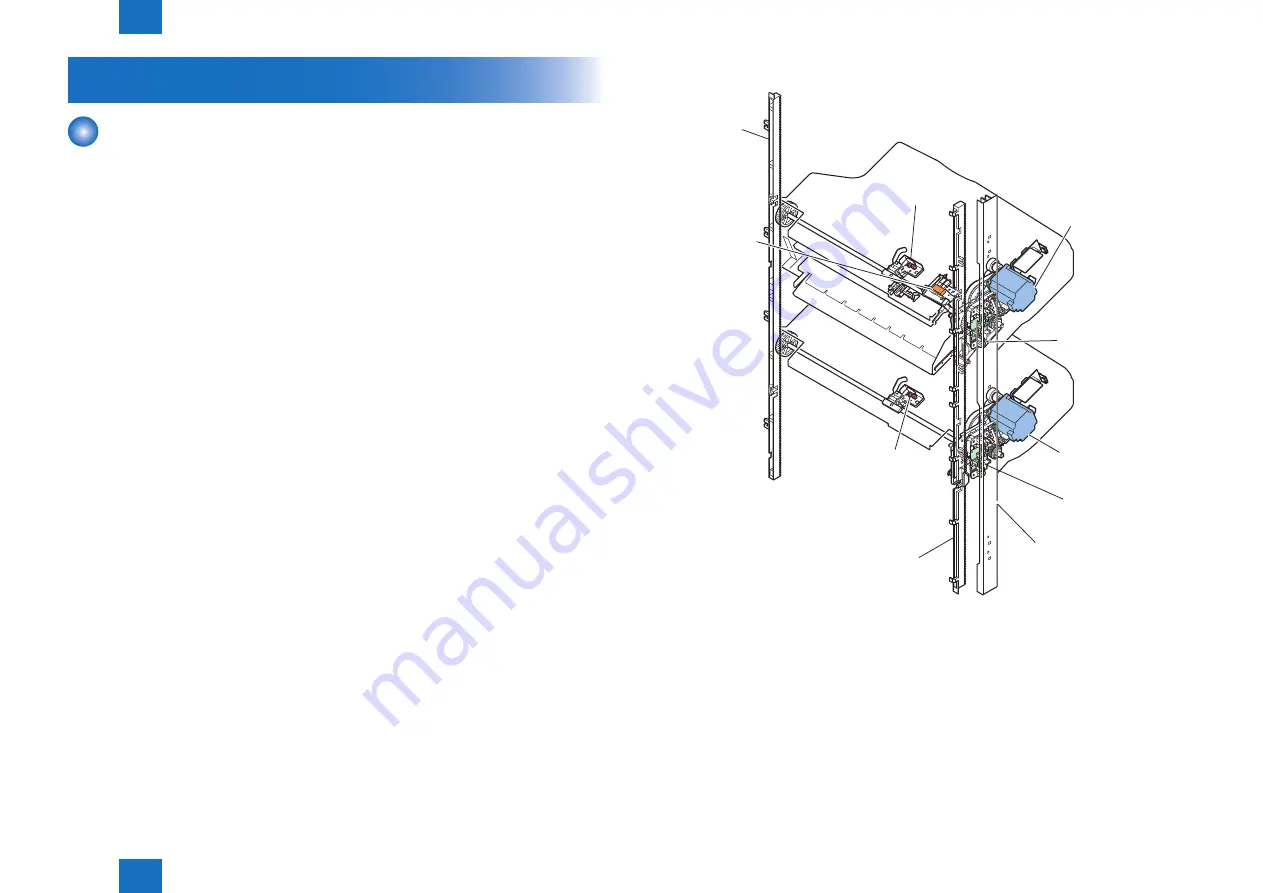
This equipment has three delivery trays. The upper tray is called escape tray, the middle tray
is called tray 1, and the lower tray is called tray2. The escape tray is fixed and tray 1 and tray
2 can move up and down independently. The escape tray has an escape tray full detector
sensor(S130). When the escape tray becomes full, the finisher controller PCB notifies the
host machine to that effect.
The finisher controller PCB controls the vertical movement of tray 1 and tray 2 by changing
the drive direction of the tray 1 shift motor (M105) and tray 2 shift motor (M217) (incorporating
a motor driver PCB).
Tray 1 paper sensor (S104) and tray 2 paper sensor (S105) are provided to detect the
presence of the paper stacked on tray 1 and tray 2.
The home position of tray 1 is detected by the tray 1 paper surface sensor (PI114) and the
home position of tray 2 is detected by the tray 2 paper surface sensor(PI115) 1. The home
position is the top surface of the paper if paper is already stacked on the tray, or the position
where the edge of the tray is detected if no paper is stacked. The tray 2 paper surface sensor
(S143) 2 detects the paper surface when 651 or more sheets are stacked in tray 2. When the
power is turned on, the finisher controller PCB drives the tray 1 shift motor (M105) and tray
2 shift motor (M217) to return the tray 1 and tray 2 to their home positions. If either tray is
already at the home position, it is moved out of the home position once and then returned to
the home position again. If both tray 1 and tray 2 are at their home positions, this operation is
performed for tray 2 and then for tray 1. If the tray specified by the host machine is tray 2, the
finisher controller PCB raises the tray so that tray 2 is at the delivery port.
When paper is stacked on either tray, the tray 1 shift motor (M105) or tray 2 shift motor (M217)
is driven a prescribed number of pulses to lower the tray. Then the tray returns to the home
position to prepare for the next stack.
The upper and lower limits of the tray are detected by three area sensors (S122, S123,
S124,S125,S126,S127) on the tray 1 and tray 2 shift area sensor PCB. The finisher controller
PCB stops driving the tray 1 shift motor (M105) and tray 2 shift motor (M217) upon detection
of the upper or lower limit of the tray. Also, the ON/OFF combinations of the area sensors
(S122, S123, S124,S125,S126,S127) are used to detect over-stacking according to the stack
height for large size and mixed stacking.
The finisher controller PCB stops sup24V to the tray 1 shift motor (M105) and stops
the finisher operation when tray 1 closing detect switch (SW110) turns ON
Tray 1 Close
Detection
Switch
Tray 1
Area Sensor PCB
Tray 1
Shift Motor
Tray 2
Shift Motor
Rack
Rack
Tray 1
Paper Sensor
Tray 2
Paper Sensor
Light-shielding plate
Tray 2
Area Sensor PCB
F-2-18
F-2-18
Summary of Contents for Staple Finisher-D1
Page 4: ...0 0 0 4 0 4 ...
Page 9: ...Safety Precautions Notes Before it Works Servicing ...
Page 59: ...3 3 Periodic Servicing Periodic Servicing List of Work for Scheduled Servicing ...
Page 144: ...5 5 Adjustment Adjustment Overview Basic Adjustment Action on parts replacement ...
Page 194: ...7 7 Appendix Appendix Service Tools General Circuit Diagram F 7 1 F 7 1 ...


