COPYRIGHT© 2001 CANON INC.
2000 2000 2000 2000
CANON SADDLE FINISHER K3/K4 REV.0 MAR. 2001
2-82
CHAPTER 2 OPERATION OVERVIEW
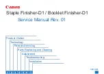
7.1.8 Punch Registration Motor (M17) / Punch Motor (M18) Drive Control
An outline of the punch registration motor (M17) and punch rotating motor (M18) drive
circuit is shown in the diagram below. M17 is a 4-phase stepping motor. Drive pulses are
sent from IC121 on the finisher controller PCB.
M18 is a DC motor. IC125 sends signals which control the motor's rotation direction and
speed.
The punch registration motor's PNHREGREF outputs signals to control the electrical cur-
rent level switching while the motors are running and also while they are in hold mode.
Each motor has three current levels for operating mode and one for hold mode.
F02-701-14
Finisher
controller
PCB
J741-A8
J741-A9
J741-A10
PCH_SFTN_CW
PCH_SFTN_CLK
PCH_SFTN_REF
J741-B14
J741-A6
J741-A7
PCH_M_CCW
PCH_M_CW
PCH_M_PWM
Q758
A*
A
B*
B
M17
24VH
3
2
4
5
1
6
Punch
registration
motor
Motor
driver PCB
Punch
rotation
motor
M18
2
1
Punch driver PCB
J744
J746
IC125