2. Installation Manual
- 12 -
(3) Cable
connections
1) Loosen the lock nut for each cable and connect the cables to the power box. Then fix
the cables by tightening the lock nuts.
Note:
To avoid the risk of damage when the cables are removed with very large force, Check
tightening torque of the bush (refer the following figure).
<Sensor cable>
<X-RAY I/F cable,
Remote cable>
2) Attach the cable clamp to the sensor cable, and then fix it to the power box using the
screw (M4 x 6 mm).
Lock nut
X-ray I/F cable
Sensor cable
Remote cable
Cable clamp
Screw (M4×6mm)
Clamp the cable’s
shield portion
Gap 1.0 to 1.5mm
No gap
Summary of Contents for CXDI-50C
Page 15: ......
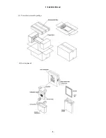
Page 23: ...2 Installation Manual 6 3 Power Box assemble package 4 Grid optional ...
Page 35: ...2 Installation Manual 18 When normal imaging When timeout due to RX_REQ not negating ...
Page 63: ...2 Installation Manual 46 Fig 3 Input parameters ...
Page 115: ...2 Installation Manual 98 2 Power Box Unit mm Mass 4 2Kg ...
Page 118: ......
Page 163: ......
Page 167: ...CXDI SYSTEM 1 2 Rev 04 Key No 5 Key No 6 Key No 7 Key No 8 Key No 9 Canon Inc ...
Page 186: ......
Page 188: ......
Page 189: ...Content 1 Gathering Information about Problems 1 2 How to back up and recover the system 3 ...


