Chapter 19
19-86
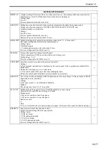
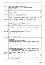
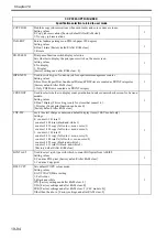
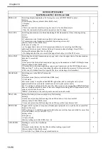
ANIM-SW
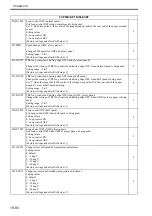
Use it to prohibit display of the Error/Jam screen while a MEAP application is in operation.
Although setting the value as '1' in COPIER > OPTION > BODY > MEAP-DSP, at the occurrence of
error/jam/alarm, the display transits to the standard screen for showing a warning.
When setting this value as '1', at the occurrence of error/jam/alarm,
- Display transition to the standard screen is prohibited.
- Warning is displayed on the MEAP screen to urge the user to contact servicing.
settings
0: off (display warning screen; default); 1: on (do not display warning screen)
2
HDD-TMP
Use it to set a level of temperature to serve as a reference for detecting a low temperature error.
The new setting will not be valid until the power switch has been turned off and then on again.
Settings
0 to 30 deg C [Factory default/After RAM clear: 2]
2
HDD-TIM
Use it to set the time interval allowed before a low temperature error is identified
The new setting will not be valid until the power switch has been turned off and then on again.
Settings
0 to 200 min [Factory default/After RAM clear: 10]
2
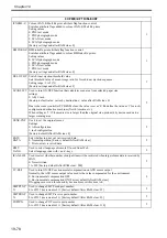
HDD-SW
Use it to enable/disable E code indication of a low temperature error
The new setting will not be valid until the power switch has been turned off and then on again
Settings
0: do not indicate
1: indicate [Factory default/After RAM clear: 0]
2
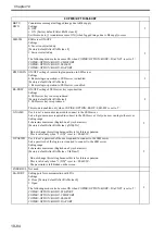
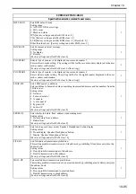
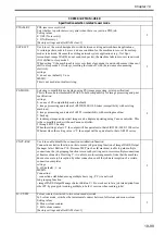
DV-RT-LG
Switching the developing assembly idle rotation time of first thing in the morning
Settings
0: 1 minute
1: 2 minutes [Factory default/After RAM clear: 0]
Default of idle rotation time is 1 minute since iR C3200/iR C3220 Dcon V12.1 to prolong life of the
process cartridge. However, use this mode to set 2 minutes if any trouble (faulty image etc.) occurs
due to reduction of the time.
2
MEAP-SSL
Use it to set an HTTPS port for MEAP.
Sets a port for the HTTPS server to use SSL in the MEAP HTTP.
Setting range
1 to 65535 [Factory default/After RAM clear: 8443]
2
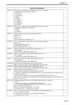
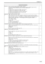
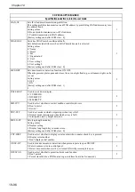
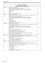
DH-TMG
Setting up a threshold for the accumulated number of outputs for the Dhalf control sequence operation
trigger.
Control
If the fixing unit is lower than a specified temperature when the machine is turned on or recovered
from the sleep mode, use this mode to make automatic full adjustments during initial multiple
rotations.
At this time, the Dhalf control is performed only if the number of outputs accumulated since the last
Dhalf control exceeds the value specified in this Service Mode.
Changing the timing of or canceling the Dhalf control (according to the number of accumulated
outputs) by using this mode can reduce the downtime in the morning. (A measure for a complaint
about the downtime in the morning)
Meanwhile, there is a possibility that gray scale (half-tone image) might be degraded when the Dhalf
control is cancelled.
With regard to the accumulated number of outputs, a small-size copy is regarded as 1 count, and a
large-size copy is regarded as 2 counts.
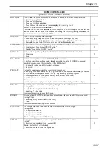
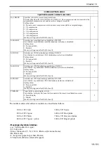
When the Dhalf control is performed first thi
2
COPIER>OPTION>BODY
Summary of Contents for Color imageRUNNER C5180 Series
Page 22: ...Chapter 1 INTRODUCTION...
Page 64: ...Chapter 2 INSTALLATION...
Page 110: ...Chapter 3 BASIC OPERATION...
Page 119: ...Chapter 4 BASIC OPERATIONS AS A PRINTER...
Page 129: ...Chapter 5 MAIN CONTROLLER...
Page 138: ...Chapter 5 5 8 F 5 8 CPU HDD ROM access to the program at time of execution...
Page 165: ...Chapter 6 ORIGINAL EXPOSURE SYSTEM...
Page 209: ...Chapter 7 IMAGE PROCESSING SYSTEM...
Page 212: ...Chapter LASER EXPOSURE 8...
Page 239: ...Chapter 9 IMAGE FORMATION...
Page 324: ...Chapter 10 PICKUP FEEDING SYSTEM...
Page 435: ...Chapter 11 FIXING SYSTEM...
Page 460: ...Chapter 11 11 23 F 11 13 SEN3 SEN2 SEN1 SEN2 SEN3 SEN1 SEN2 SEN3 SEN1...
Page 491: ...Chapter 12 EXTERNALS CONTROLS...
Page 498: ...Chapter 12 12 5 F 12 2 FM1 FM7 FM9 FM2 FM13 FM14 FM12 FM11 FM10 FM5 FM3 FM4 FM8 FM6...
Page 512: ...Chapter 12 12 19 2 Remove the check mark from SNMP Status Enabled F 12 10...
Page 553: ...Chapter 13 MEAP...
Page 557: ...Chapter 14 RDS...
Page 569: ...Chapter 15 MAINTENANCE INSPECTION...
Page 578: ...Chapter 16 STANDARDS ADJUSTMENTS...
Page 597: ...Chapter 17 CORRECTING FAULTY IMAGES...
Page 612: ...Chapter 17 17 14 F 17 7 PLG1 ELCB1 SP1 H4 H3 H2 H1 H1 H2 LA1...
Page 617: ...Chapter 18 SELF DIAGNOSIS...
Page 644: ...Chapter 19 SERVICE MODE...
Page 778: ...Chapter 20 UPGRADING...
Page 823: ...Chapter 21 SERVICE TOOLS...
Page 828: ...APPENDIX...
Page 851: ......


