Chapter 19
19-83
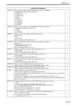
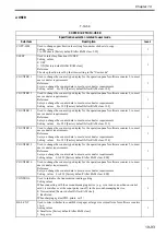
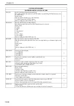
NS-PLN
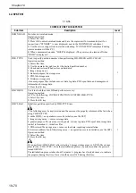
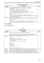
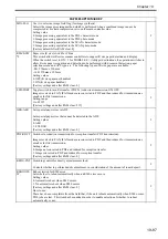
Use it to set PLAIN LOGIN under SMTP authentication.
<environment in which communication packages are not subjected to coding>
setting
0: dependent on SMTP server
1: disable
2
NS-LGN
Use it to set LOGIN authentication under SMTP authentication.
setting
0: dependent on SMTP server
1: disable
2
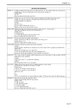
MEAP-PN
Setting the port No. of HTTP server used for MEAP application
Settings 0 to 65535 [Factory default/After RAM clear: 8000]
Referemnce:
Do not use 1 to 1023 excepting 80 (HTTP) if specifying the port No. of HTTP server as MEAP port.
(Because standard servers use numbers in this range.)
2
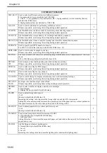
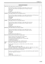
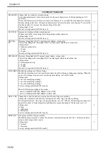
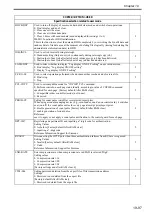
TMIC-BK
Use it to set the correction along the trailing edge for BkLUT and BkLUT for PDL (Tmic).
Settings
0: PDL BK_LUT end correction ON; copy Bk_LUT end correction OFF
1: PDL BK_LUT end correction OFF; copy Bk_LUT end correction OFF
2: PDL BK_LUT end correction ON; copy Bk_LUT end correction ON (default)
3: PDL BK_LUT end correction OFF; copy Bk_LUT end correction ON
[Factory default/After RAM clear: 2]
2
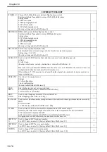
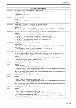
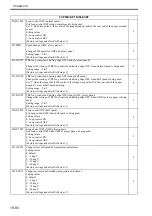
SVMD-ENT Switching the method of entering the Service Mode.
Setting Values
0: [User Mode key] -> Press [2] and [8] simultaneously -> [User Mode key] [Factory default/After
RAM clear]
1: [User Mode key] -> Press [4] and [9] simultaneously -> [User Mode key]
Reference Information Support for Siemens
2
DH-MODE
Patch Data (high density side) Used in D-half Except in Full Correction
Change the default setting so that the readout collected from D-half at time of full correction will be
substituted for the patch on the high density side at time of D-half (other than in full correction).
Settings
0: use patch image read data of full correction (at time of shipment/upon RAM initialization)
1: do not use patch image read data of full correction
[Factory default/After RAM clear: 0]
2
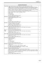
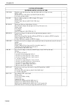
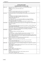
LSUB-
DWY
Switching DC bias voltage of the lower auxiliary brush
Settings:
0: Bias is standard
1: Bias is reduced [Factory default/After RAM clear: 0]
Increasing DC bias of the lower auxiliary brush has the effect of retaining/charging remaining transfer
toner. (Countermeasures against fogged image)
However, faulty image such as mark of the auxiliary brush and filming may occur as a result. Set this
mode to '1' if such faulty image occurs.
2
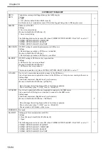
LSUB-
DWM
Switching DC bias voltage of the lower auxiliary brush
Settings:
0: Bias is standard
1: Bias is reduced [Factory default/After RAM clear: 0]
Increasing DC bias of the lower auxiliary brush has the effect of retaining/charging remaining transfer
toner. (Countermeasures against fogged image)
However, faulty image such as mark of the auxiliary brush and filming may occur as a result. Set this
mode to '1' if such faulty image occurs.
2
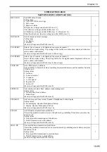
LSUB-
DWC
Switching DC bias voltage of the lower auxiliary brush
Settings:
0: Bias is standard
1: Bias is reduced [Factory default/After RAM clear: 0]
Increasing DC bias of the lower auxiliary brush has the effect of retaining/charging remaining transfer
toner. (Countermeasures against fogged image)
However, faulty image such as mark of the auxiliary brush and filming may occur as a result. Set this
mode to '1' if such faulty image occurs.
2
COPIER>OPTION>BODY
Summary of Contents for Color imageRUNNER C5180 Series
Page 22: ...Chapter 1 INTRODUCTION...
Page 64: ...Chapter 2 INSTALLATION...
Page 110: ...Chapter 3 BASIC OPERATION...
Page 119: ...Chapter 4 BASIC OPERATIONS AS A PRINTER...
Page 129: ...Chapter 5 MAIN CONTROLLER...
Page 138: ...Chapter 5 5 8 F 5 8 CPU HDD ROM access to the program at time of execution...
Page 165: ...Chapter 6 ORIGINAL EXPOSURE SYSTEM...
Page 209: ...Chapter 7 IMAGE PROCESSING SYSTEM...
Page 212: ...Chapter LASER EXPOSURE 8...
Page 239: ...Chapter 9 IMAGE FORMATION...
Page 324: ...Chapter 10 PICKUP FEEDING SYSTEM...
Page 435: ...Chapter 11 FIXING SYSTEM...
Page 460: ...Chapter 11 11 23 F 11 13 SEN3 SEN2 SEN1 SEN2 SEN3 SEN1 SEN2 SEN3 SEN1...
Page 491: ...Chapter 12 EXTERNALS CONTROLS...
Page 498: ...Chapter 12 12 5 F 12 2 FM1 FM7 FM9 FM2 FM13 FM14 FM12 FM11 FM10 FM5 FM3 FM4 FM8 FM6...
Page 512: ...Chapter 12 12 19 2 Remove the check mark from SNMP Status Enabled F 12 10...
Page 553: ...Chapter 13 MEAP...
Page 557: ...Chapter 14 RDS...
Page 569: ...Chapter 15 MAINTENANCE INSPECTION...
Page 578: ...Chapter 16 STANDARDS ADJUSTMENTS...
Page 597: ...Chapter 17 CORRECTING FAULTY IMAGES...
Page 612: ...Chapter 17 17 14 F 17 7 PLG1 ELCB1 SP1 H4 H3 H2 H1 H1 H2 LA1...
Page 617: ...Chapter 18 SELF DIAGNOSIS...
Page 644: ...Chapter 19 SERVICE MODE...
Page 778: ...Chapter 20 UPGRADING...
Page 823: ...Chapter 21 SERVICE TOOLS...
Page 828: ...APPENDIX...
Page 851: ......


