


Chapter 6
6-19
(2) between sheets (dust correction)
The machine does not move the xenon lamp for dust detection.
If dust is detected between sheets, the machine executes dust correction by making correction on the pixels
on both sides of the area where dust is found.
MEMO:
COPIER > OPTION > BODY > DFDST-L1 (level 1)
(adjustment of dust detection level between sheets)
COPIER > OPTION > BODY > DFDST-L2 (level 1)
(adjustment of dust detection at job end)
6.3.5.2 White Plate Dust Detection Control
The machine uses a fan to cool the inside of the reader unit to prevent overheating otherwise caused by the xenon
lamp in stream reading mode. The fact, however, can cause stray dust inside the reader unit to collect on the
white plate, showing up as lines in output images.
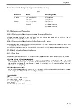
1. Timing of Control
(1) Before a Job
(a) white plate dust detection
(b) white plate dust correction
(2) After a Job
(a) white plate dust detection
(b) white plate dust correction
F-6-29
2. Particulars of Control
(1) White Plate Dust Detection
The machine compares the shading coefficient obtained from shift shading and the shading coefficient
obtained from fixed shading to identify the presence/absence of dust and, if any, coordinates and width of
the area.
(2) White Plate Dust Correction
If the machine detects dust as a result of white plate dust detection, it corrects the shading coefficient of
the area using the shading coefficient of both sides so as to decrease the effects of the presence of dust. It
executes shading correction using the coefficient it obtains after correction.
If the result of white plate dust detection indicates the presence of dust, the shading coefficient of the area
in question will be corrected by the coefficients of its adjacent areas during shading correction with the
aim of reducing the effects of the presence of dust. Thereafter, shading correction will be executed using
the corrected coefficient.
Dust detection
Dust detection
Start key
ON
1st
SCAN
2nd
SCAN
Summary of Contents for Color imageRUNNER C5180 Series
Page 22: ...Chapter 1 INTRODUCTION...
Page 64: ...Chapter 2 INSTALLATION...
Page 110: ...Chapter 3 BASIC OPERATION...
Page 119: ...Chapter 4 BASIC OPERATIONS AS A PRINTER...
Page 129: ...Chapter 5 MAIN CONTROLLER...
Page 138: ...Chapter 5 5 8 F 5 8 CPU HDD ROM access to the program at time of execution...
Page 165: ...Chapter 6 ORIGINAL EXPOSURE SYSTEM...
Page 209: ...Chapter 7 IMAGE PROCESSING SYSTEM...
Page 212: ...Chapter LASER EXPOSURE 8...
Page 239: ...Chapter 9 IMAGE FORMATION...
Page 324: ...Chapter 10 PICKUP FEEDING SYSTEM...
Page 435: ...Chapter 11 FIXING SYSTEM...
Page 460: ...Chapter 11 11 23 F 11 13 SEN3 SEN2 SEN1 SEN2 SEN3 SEN1 SEN2 SEN3 SEN1...
Page 491: ...Chapter 12 EXTERNALS CONTROLS...
Page 498: ...Chapter 12 12 5 F 12 2 FM1 FM7 FM9 FM2 FM13 FM14 FM12 FM11 FM10 FM5 FM3 FM4 FM8 FM6...
Page 512: ...Chapter 12 12 19 2 Remove the check mark from SNMP Status Enabled F 12 10...
Page 553: ...Chapter 13 MEAP...
Page 557: ...Chapter 14 RDS...
Page 569: ...Chapter 15 MAINTENANCE INSPECTION...
Page 578: ...Chapter 16 STANDARDS ADJUSTMENTS...
Page 597: ...Chapter 17 CORRECTING FAULTY IMAGES...
Page 612: ...Chapter 17 17 14 F 17 7 PLG1 ELCB1 SP1 H4 H3 H2 H1 H1 H2 LA1...
Page 617: ...Chapter 18 SELF DIAGNOSIS...
Page 644: ...Chapter 19 SERVICE MODE...
Page 778: ...Chapter 20 UPGRADING...
Page 823: ...Chapter 21 SERVICE TOOLS...
Page 828: ...APPENDIX...
Page 851: ......