Document type:
Title:
Revision date:
Revision:
User's Manual (MUT)
Mod. SY2527, Universal Multichannel Power Supply System
27/11/2000
0
NPO:
Filename:
Number of pages:
Page:
00103/97:2527y.MUTx/00
SY2527USERMANUAL_REV0.DOC
84
27
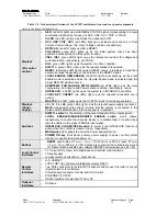
At normal operation, this signal is True and the relevant green LED is ON.
This output signal becomes false either as the Fan failure LED is alight or as the Power
failure LED is alight. As the condition which caused the CHECK PASSED being FALSE
is remove, the CHECK PASSED signal becomes true again.
4.3.7
GEN
GEN
(GENERAL STATUS) output signal is True (and relevant red LED on) according to
a logic combination of OVC, UNV, OVV and TRIP. The logic combination of these
conditions is defined by the user via the
Status
command in the
Utility
menu.
Refer to § 7.1.17, p.60 for further details.
4.3.8
CH-ON
CH-ON
(CHANNEL ON) output signal is True (and the relevant red LED on) as at least
one channel is ON (i.e. the channels are enabled and the POWER parameter of that
channel is set to ON; see § 4.4.14, p.31).
4.3.9
Over Temperature
Over Temperature
condition occurs when there is at least one board at a temperature
out of the range
TMIN
÷
TMAX
, where
TMIN
and
TMAX
are two parameters depending
on the board type (e.g., in the Mod. A1733
TMIN
= 5°C and
TMAX
= 65°C).
As the Over Temperature condition is reached, the relevant front panel LED lights up.
4.3.10
Fan Failure
Fan
Failure
condition occurs when at least one of the 3 fans of the system has stopped
or is turning below 20% of normal speed.
As the Fan Failure condition is reached, the relevant front panel LED lights up.
4.3.11
Pwr Failure
Power
Failure
condition occurs when there is a fault in the voltage supplies at the
±
12 V, +5 V or +48 V level.
As the Power Failure condition is reached, the relevant front panel LED lights up.


