Document type:
Title:
Revision date:
Revision:
User's Manual (MUT)
Mod. SY2527, Universal Multichannel Power Supply System
27/11/2000
0
NPO:
Filename:
Number of pages:
Page:
00103/97:2527y.MUTx/00
SY2527USERMANUAL_REV0.DOC
84
67
•
PC Front Panel Reset
, i.e. an reset of the CPU section sent via front panel;
•
BP User Software Reset
, i.e. an auto-reset of the board section due to a
command forwarded by the user (not yet implemented);
•
BP Front Panel Reset
, i.e. a reset of the board section sent via front panel;
•
BP WatchDog
, i.e. a reset of the board section due to a firmware control failure.
If more than one reset types are selected, the RESET FLAG signal will be asserted at
the first occurrence of any of them.
This window allows also to enable the relevant reset condition, i.e. if a condition is
tagged with the asterisk it is enabled; if it is not tagged, it is disabled.
For example, if
the PC front panel reset is not tagged with the asterisk, a signal sent through the
front panel connector does not reset the CPU.
Default setting is
PC
Front Panel Reset
and
BP
Front Panel Reset
enabled.
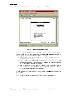
To select one or more of these conditions, move through the rows with the Up/Down
arrow keys, tag the chosen conditions with the asterisk by the Left/Right arrow keys and
then select OK and press ENTER.
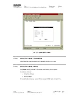
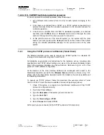
Default settings are shown in the figure below: these correspond to assert TRUE the
RESET FLAG output signal on the occurrence of a CPU RESET (PC Reset) from the
front panel and on the occurrence of a boards RESET (BP Reset) from the front panel.
For details on the RESET signal please refer to § 4.2.7.
Fig. 7.20 – Reset Flag pop-up Window


