Display Unit DDU 7
Display Configuration | en
43
Bosch Motorsport
Manual
04.02.2019 | V 02 |
3.
Click ‘Ok’ when done.
A graphic shows the connection between the input and output channels. The measurement
channel can now be used in the shift LED configuration.
8.3.3
Creating customized LED pattern
You can create your own LED pattern with an individually created condition. The LEDs flash if
the condition becomes true.
1.
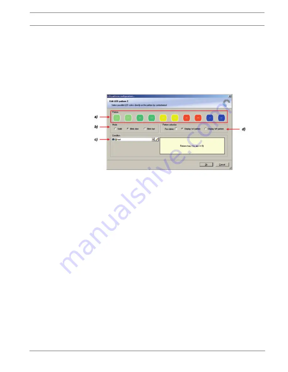
Click on the button ‘Add pattern’ in the display view. The LED pattern configuration
window appears.
a) Choose the number and color of the LEDs by right-clicking.
b) Select if the LEDs blink or do not blink.
c) Choose the condition when the LEDs will flash.
Create a condition using the Condition Creator. For more information see chapter ‘Creating a new
condition channel’.
Choose an existing condition
d) Check the box to show a demo of the LEDs (Important to check blinking). To create a LED that alternately
blinks in two different colors, choose ‘Display “on” pattern’ and define the LEDs in the one color. Then choose
‘Display “off” pattern’ and define the LEDs in the other color.
2.
Click ‘OK’ when done.
3.
The configuration is displayed in the DDU 7 LED Configuration window.
8.3.4
Assigning display pattern priority
Assigning display pattern priority
You can assign the priority of the created display pattern and shift lights.
The 1st display pattern is activated before all following pattern if its condition is ‘true’. The
2nd display pattern is only activated if the condition of the 1st display pattern is ‘false’ or the
LEDs of the 1st display pattern are transparent.
Change the priority by clicking the ‘Move up’ or ‘Move down’ button.
Summary of Contents for DDU 7
Page 1: ...Display Unit DDU 7 Manual V 02 2 4 2019 ...
Page 2: ......
Page 139: ...Display Unit DDU 7 Firmware en 139 Bosch Motorsport Manual 04 02 2019 V 02 ...
Page 155: ......


