S2000R
S2000R-SMK
61
www.bolid.ru
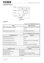
Table 10-16. Link Quality Indication
LED Performance
Condition
Flashes with green
Strong signal
Flashes with green and red
Normal signal
Flashes with red
Weak signal (not recommended to install)
Shows solid red light for 1 s
No communications or the device is not connected to
the ARR32
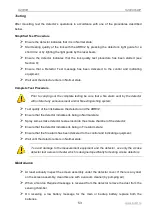
Getting Started
Open the detector case.
Remove the insulating spacer from the battery holder and wait until depassivation is
completed.
The depassivation procedure activates batteries after long term storage and can take up to 5 minutes.
The process of depassivation is indicated as shown in Table 10-15. If depassivation fails the device
indicates low battery condition.
Connecting and Programming
Connect the detector to the ARR32 and set its parameters in the configuration of the polling loop
controller as discussed in Sections 6, 7, and 8 of this Manual.
Tamper Switch and Tearing Protection
By default, the detector monitors only tamper switch conditions. To provide monitoring for tearing the
detector from its mounting point, remove the pre-formed knock-out plug on the base of the Detector
and release the spring.
External Monitored Circuit
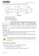
The S2000R-SMK provides connecting wired intrusion and fire detectors with alarm output of dry
contact type. The detectors are not supposed to be powered via the Monitored Circuit.
To activate analysis of the monitored circuit conditions, either close the jumper XP1 (see Figure 10-8)
and re-connect the detector to the ARR32 or set the relevant parameter using S2000R Configurator
(see Section 7). In last case the jumper can be not closed.
If monitoring the external circuit is activated then the Monitoring Circuit occupies the address in the
polling loop address space which follows the address of the relevant S2000R-SMK.
If the Monitored Circuit is not in use, it is recommended to disable monitoring in order to clear the
address space of the polling loop and to extend the expected life time of the detector’s battery.

