- 193 -
ENG
HEAD FITTING
D
Before assembling the head, replace the seal (12).
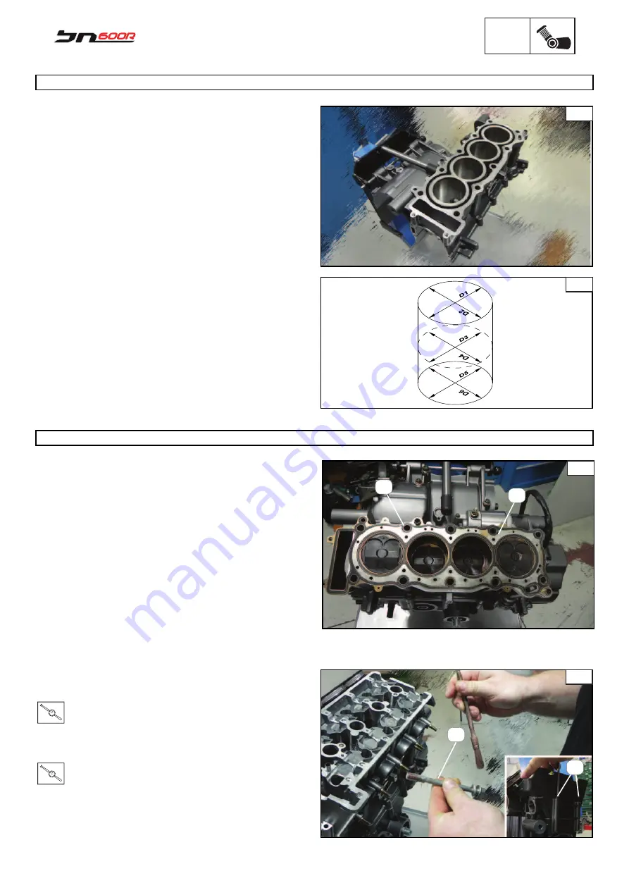
Make sure that the centering pin (11) is in position Fig. C
To assemble the head, fi rst tighten the 10 fastening screws (X)
Fig. D and then the two allen screws (6).
NOTE
During assembly of the head. lubricate the head screws with
copper grease.
Tighten the screws (X) to the following torque:
T.R.
Torque 55 N*m
Tighten the screws (6) to the following torque:
T.R.
Torque 12 N*m
X
6
HEAD TIMING GEAR
C
12
11
CYLINDER CHECK
The following procedure applies the whole cylinder group.
Check:
•
the walls of the cylinder Fig.A
If there are any vertical lines, replace the cylinder and the piston
all together and the relevant clips.
•
The cooling cavity of the cylinder, in case of build up, remo-
ve scale deposits.
Measure:
•
Cylinder stroke Fig. B
Take different measurements at a distance f 10-43-90 mm from
the head coupling.
The highest value is considered when calculating wear limits.
CYLINDER Bore (C)= 65x45.2
C=Max D1 or D2 65
A
B
- 0.002
- 0.003
mm
Summary of Contents for 2014 BN600
Page 1: ...SERVICE STATION MANUAL code Pure Passion since 1911 ...
Page 6: ...GEN INFO 5 GEN INFO General Information CHAPTER 1 ...
Page 19: ...SPEC 18 SPEC Specifications CHAPTER 2 ...
Page 37: ...CHK ADJ 36 CHK ADJ Inspections and Periodic Adjustments CHAPTER 3 ...
Page 40: ...CHK ADJ 39 NOTES ...
Page 80: ...CHAS 79 Frame CHAPTER 4 CHAS ...
Page 175: ... 174 ENG ENG Engine CHAPTER 5 ...


