


14-4
9424200996
Inverse Overcurrent (51) Protection
BE1-11
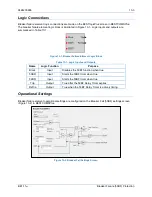
m
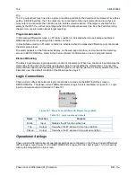
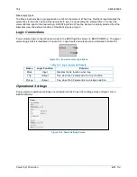
elements to annunciate the condition, control other elements in logic, and start the fault recorder (logic
element FAULTTRIG).
Assertion of the Pickup output initiates a timer that begins timing to a trip. The duration of the timer is
established by the Time Dial and Curve settings. A Time Dial setting of zero (0) makes the 51 element
instantaneous with no intentional time delay.
If the pickup condition subsides before the calculated inverse time expires, the timer and Pickup outputs
are reset, no corrective action is taken, and the element is rearmed for any other occurrences of
overcurrent.
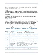
Trip
The Trip output becomes true if an overcurrent pickup condition persists for the duration of the calculated
inverse time. In BESTlogic
Plus
, the Trip output can be connected to other logic elements and to a
physical relay output to annunciate the condition and to initiate corrective action. If a target is enabled for
the element, the BE1-11
m
will record a target when the Trip output becomes true. See the
Fault
Reporting
chapter for more information about target reporting.
Voltage Restraint Mode (51/27R)
When a 51 element is set for 3 Phase, IA, IB, or IC mode, the 51 element can be set for voltage control or
voltage restraint mode of operation. This feature is used to allow increased phase overcurrent sensitivity
while providing security from operation due to load current.
A Voltage Restraint threshold of zero (0) disables voltage restraint/control and allows the 51 element to
operate normally.
Note
BE1-11
m
protection systems enabled for IEC-61850 communication
(style Mxxxx5xxxxxxxx) do not allow voltage controlled or restrained
overcurrent elements. Blocking a 51 with an Undervoltage (27)
element may allow control pending application requirements.
Control Mode
When set for Control mode of operation, the 51 element is disabled until the measured voltage drops
below the Voltage Restraint threshold. Thus, as long as the voltage on the appropriate phase is above the
Voltage Restraint threshold, the 51 element will be blocked. When set for this mode of operation, the 51
Pickup setting is typically set near or below load current levels.
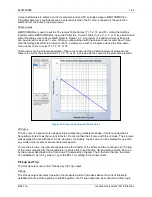
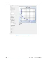
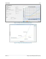
Restraint Mode
When set for Restraint mode of operation, the pickup of the 51 element is adjusted based upon the
magnitude of the measured voltage. Figure 14-2 shows how the 51 Pickup setting is adjusted in response
to the measured voltage level. Equation 14-3 determines the pickup level for the 51 element when the
measured voltage is between 25% and 100% of the Voltage Restraint threshold. Below 25%, the pickup
level stays at 25%. Above 100%, the pickup level stays at 100%. For example, if the Voltage Restraint
threshold is set for 120 V and the measured voltage on the appropriate phase is 100 V (83% of the
Voltage Restraint threshold), the phase overcurrent pickup level will be reduced to 83% of its setting.
When set for this mode of operation, the 51 element Pickup setting is typically set above worst case, load
current levels.
Summary of Contents for BE1-11m
Page 8: ...vi 9424200996 Revision History BE1 11m...
Page 12: ...x 9424200996 Contents BE1 11m...
Page 21: ...9424200996 1 9 BE1 11m Introduction Figure 1 1 Style Chart...
Page 22: ...1 10 9424200996 Introduction BE1 11m...
Page 40: ...3 6 9424200996 Controls and Indicators BE1 11m Figure 3 3 Front Panel Display Setup Screen...
Page 54: ...5 6 9424200996 Phase Undervoltage 27P Protection BE1 11m...
Page 56: ...6 2 9424200996 Negative Sequence Voltage 47 Protection BE1 11m...
Page 61: ...9424200996 7 5 BE1 11m Phase Overvoltage 59P Protection Figure 7 3 Overvoltage Settings Screen...
Page 62: ...7 6 9424200996 Phase Overvoltage 59P Protection BE1 11m...
Page 68: ...8 6 9424200996 Auxiliary Overvoltage 59X Protection BE1 11m...
Page 80: ...12 4 9424200996 Instantaneous Overcurrent 50 Protection BE1 11m...
Page 84: ...13 4 9424200996 Breaker Failure 50BF Protection BE1 11m...
Page 92: ...14 8 9424200996 Inverse Overcurrent 51 Protection BE1 11m...
Page 105: ...9424200996 18 3 BE1 11m Power Factor 55 Protection Figure 18 2 Power Factor Settings Screen...
Page 106: ...18 4 9424200996 Power Factor 55 Protection BE1 11m...
Page 110: ...19 4 9424200996 Resistance Temperature Detector 49RTD Protection BE1 11m...
Page 118: ...20 8 9424200996 Thermal Curve 49TC Protection BE1 11m...
Page 122: ...22 2 9424200996 Starts per Time Interval 66 Protection BE1 11m...
Page 124: ...23 2 9424200996 Restart Inhibit Protection BE1 11m...
Page 140: ...28 4 9424200996 Breaker Control Switch 101 BE1 11m...
Page 148: ...29 8 9424200996 Setting Groups BE1 11m...
Page 156: ...30 8 9424200996 Metering BE1 11m Figure 30 11 RTD Meter Screen...
Page 158: ...31 2 9424200996 Digital Points BE1 11m Figure 31 2 Digital Points Monitor Screen...
Page 177: ...9424200996 34 5 BE1 11m Motor Reporting Figure 34 9 Learned Motor Data Screen...
Page 178: ...34 6 9424200996 Motor Reporting BE1 11m...
Page 184: ...35 6 9424200996 Alarms BE1 11m...
Page 186: ...36 2 9424200996 Differential Reporting BE1 11m...
Page 196: ...38 4 9424200996 Demands BE1 11m...
Page 198: ...39 2 9424200996 Load Profile BE1 11m...
Page 208: ...41 6 9424200996 Trip Circuit Monitor 52TCM BE1 11m...
Page 212: ...42 4 9424200996 Fuse Loss 60FL BE1 11m...
Page 218: ...43 6 9424200996 BESTnet Plus BE1 11m Figure 43 8 Power Quality Page...
Page 221: ...9424200996 44 3 BE1 11m Mounting Figure 44 3 Case Side Dimensions...
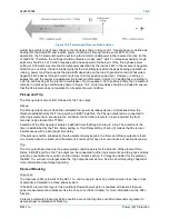
Page 235: ...9424200996 45 5 BE1 11m Terminals and Connectors Figure 45 7 Example of Reversed CT Polarity...
Page 236: ...45 6 9424200996 Terminals and Connectors BE1 11m...
Page 269: ...9424200996 48 15 BE1 11m BESTlogic Plus Figure 48 4 Logic Page 1 for Default Logic...
Page 288: ...49 10 9424200996 Communication BE1 11m Figure 49 14 Modbus Mapping Screen...
Page 306: ...52 4 9424200996 Device Information BE1 11m...
Page 314: ...53 8 9424200996 Configuration BE1 11m Figure 53 3 Display Units Screen...
Page 318: ...54 4 9424200996 Introduction to Testing BE1 11m...
Page 330: ...56 6 9424200996 Commissioning Testing BE1 11m...
Page 336: ...58 4 9424200996 Phase Undervoltage 27P Test BE1 11m...
Page 340: ...59 4 9424200996 Phase Overvoltage 59P Test BE1 11m...
Page 352: ...60 12 9424200996 Auxiliary Overvoltage 59X Test BE1 11m...
Page 360: ...61 8 9424200996 Frequency 81 Test BE1 11m...
Page 364: ...62 4 9424200996 Instantaneous Undercurrent 37 Test BE1 11m...
Page 376: ...63 12 9424200996 Instantaneous Overcurrent 50 Test BE1 11m...
Page 396: ...65 16 9424200996 Inverse Overcurrent 51 Test BE1 11m...
Page 408: ...67 6 9424200996 Power 32 Test BE1 11m...
Page 412: ...68 4 9424200996 Loss of Excitation Reverse Var Based 40Q Test BE1 11m...
Page 426: ...70 10 9424200996 Thermal Curve 49TC Test BE1 11m...
Page 432: ...72 4 9424200996 Starts per Time Interval 66 Test BE1 11m...
Page 436: ...73 4 9424200996 Restart Inhibit Test BE1 11m...
Page 440: ...74 4 9424200996 Virtual Control Switches 43 Test BE1 11m...
Page 450: ...75 10 9424200996 Logic Timers 62 Test BE1 11m...
Page 464: ...79 8 9424200996 Troubleshooting BE1 11m...
Page 480: ...80 16 9424200996 Specifications BE1 11m...
Page 600: ...84 56 9424200996 Settings Calculation Examples BE1 11m Figure 84 70 Logic Page 4 Part 1...
Page 602: ...84 58 9424200996 Settings Calculation Examples BE1 11m...
Page 608: ...85 6 9424200996 BESTCOMSPlus Settings Loader Tool BE1 11m...
Page 609: ......