


9424200996
48-13
BE1-11
m
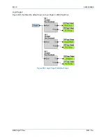
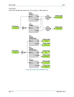
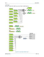
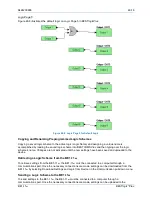
BESTlogic
™
Plus
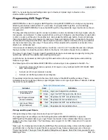
Name
Description
Symbol
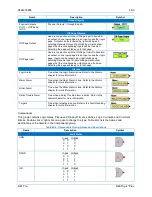
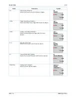
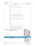
TARGETRESET
Target Reset. The Reset input is positive-edge triggered.
Refer to the
Fault Reporting
chapter.
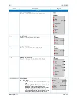
USERALARMx
User Programmable Alarms 1 through 16.
Refer to the
Alarms
chapter.
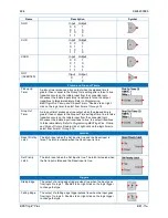
USERTARGx
User Programmable Targets 1 through 12.
Refer to the
Targets
chapter.
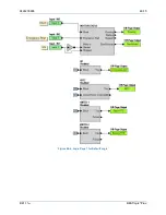
Logic Schemes
A logic scheme is a group of logic variables that defines the operation of a BE1-11
m
. Each logic scheme
is given a unique name. This gives you the ability to select a specific scheme and be confident that the
selected scheme is in operation. One logic scheme is configured for typical control applications and is the
default active logic scheme. Only one logic scheme can be active at a given time. In most applications,
preprogrammed logic schemes eliminate the need for custom programming. Preprogrammed logic
schemes can provide more inputs, outputs, or features than are needed for a particular application. This
is because a preprogrammed scheme is designed for a large number of applications with no special
programming required. Unneeded logic block outputs can be left open to disable a function or a function
block can be disabled through operating settings.
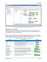
When a custom logic scheme is required, programming time is reduced by modifying the default logic
scheme.
Default Logic Scheme
All BE1-11
m
protection systems are delivered with the default logic scheme pre-loaded in memory
.
If the
function block configuration and output logic of the default logic scheme meets the requirements of your
application, then only the operating settings (power system parameters and threshold settings) need to be
adjusted before placing the BE1-11
m
in service.
Details of Default Logic Scheme
describes the characteristics of the logic scheme and how it combines to
create a Motor Protection System. A detailed description of the default scheme is also provided.
The default logic scheme is designed to accommodate most common motor protection schemes. The
protection engineer can adapt it by changing the function block operation and settings. This eliminates the
need to create a custom logic scheme.
It should be noted that the default logic scheme also illustrates typical ways of using or controlling various
functions. The user can choose to create a custom logic scheme by mixing the logic from the default
scheme. The flexibility of BESTlogic
Plus
allows the protection engineer to create a custom scheme that
exactly meets the requirements of the application.
Summary of Contents for BE1-11m
Page 8: ...vi 9424200996 Revision History BE1 11m...
Page 12: ...x 9424200996 Contents BE1 11m...
Page 21: ...9424200996 1 9 BE1 11m Introduction Figure 1 1 Style Chart...
Page 22: ...1 10 9424200996 Introduction BE1 11m...
Page 40: ...3 6 9424200996 Controls and Indicators BE1 11m Figure 3 3 Front Panel Display Setup Screen...
Page 54: ...5 6 9424200996 Phase Undervoltage 27P Protection BE1 11m...
Page 56: ...6 2 9424200996 Negative Sequence Voltage 47 Protection BE1 11m...
Page 61: ...9424200996 7 5 BE1 11m Phase Overvoltage 59P Protection Figure 7 3 Overvoltage Settings Screen...
Page 62: ...7 6 9424200996 Phase Overvoltage 59P Protection BE1 11m...
Page 68: ...8 6 9424200996 Auxiliary Overvoltage 59X Protection BE1 11m...
Page 80: ...12 4 9424200996 Instantaneous Overcurrent 50 Protection BE1 11m...
Page 84: ...13 4 9424200996 Breaker Failure 50BF Protection BE1 11m...
Page 92: ...14 8 9424200996 Inverse Overcurrent 51 Protection BE1 11m...
Page 105: ...9424200996 18 3 BE1 11m Power Factor 55 Protection Figure 18 2 Power Factor Settings Screen...
Page 106: ...18 4 9424200996 Power Factor 55 Protection BE1 11m...
Page 110: ...19 4 9424200996 Resistance Temperature Detector 49RTD Protection BE1 11m...
Page 118: ...20 8 9424200996 Thermal Curve 49TC Protection BE1 11m...
Page 122: ...22 2 9424200996 Starts per Time Interval 66 Protection BE1 11m...
Page 124: ...23 2 9424200996 Restart Inhibit Protection BE1 11m...
Page 140: ...28 4 9424200996 Breaker Control Switch 101 BE1 11m...
Page 148: ...29 8 9424200996 Setting Groups BE1 11m...
Page 156: ...30 8 9424200996 Metering BE1 11m Figure 30 11 RTD Meter Screen...
Page 158: ...31 2 9424200996 Digital Points BE1 11m Figure 31 2 Digital Points Monitor Screen...
Page 177: ...9424200996 34 5 BE1 11m Motor Reporting Figure 34 9 Learned Motor Data Screen...
Page 178: ...34 6 9424200996 Motor Reporting BE1 11m...
Page 184: ...35 6 9424200996 Alarms BE1 11m...
Page 186: ...36 2 9424200996 Differential Reporting BE1 11m...
Page 196: ...38 4 9424200996 Demands BE1 11m...
Page 198: ...39 2 9424200996 Load Profile BE1 11m...
Page 208: ...41 6 9424200996 Trip Circuit Monitor 52TCM BE1 11m...
Page 212: ...42 4 9424200996 Fuse Loss 60FL BE1 11m...
Page 218: ...43 6 9424200996 BESTnet Plus BE1 11m Figure 43 8 Power Quality Page...
Page 221: ...9424200996 44 3 BE1 11m Mounting Figure 44 3 Case Side Dimensions...
Page 235: ...9424200996 45 5 BE1 11m Terminals and Connectors Figure 45 7 Example of Reversed CT Polarity...
Page 236: ...45 6 9424200996 Terminals and Connectors BE1 11m...
Page 269: ...9424200996 48 15 BE1 11m BESTlogic Plus Figure 48 4 Logic Page 1 for Default Logic...
Page 288: ...49 10 9424200996 Communication BE1 11m Figure 49 14 Modbus Mapping Screen...
Page 306: ...52 4 9424200996 Device Information BE1 11m...
Page 314: ...53 8 9424200996 Configuration BE1 11m Figure 53 3 Display Units Screen...
Page 318: ...54 4 9424200996 Introduction to Testing BE1 11m...
Page 330: ...56 6 9424200996 Commissioning Testing BE1 11m...
Page 336: ...58 4 9424200996 Phase Undervoltage 27P Test BE1 11m...
Page 340: ...59 4 9424200996 Phase Overvoltage 59P Test BE1 11m...
Page 352: ...60 12 9424200996 Auxiliary Overvoltage 59X Test BE1 11m...
Page 360: ...61 8 9424200996 Frequency 81 Test BE1 11m...
Page 364: ...62 4 9424200996 Instantaneous Undercurrent 37 Test BE1 11m...
Page 376: ...63 12 9424200996 Instantaneous Overcurrent 50 Test BE1 11m...
Page 396: ...65 16 9424200996 Inverse Overcurrent 51 Test BE1 11m...
Page 408: ...67 6 9424200996 Power 32 Test BE1 11m...
Page 412: ...68 4 9424200996 Loss of Excitation Reverse Var Based 40Q Test BE1 11m...
Page 426: ...70 10 9424200996 Thermal Curve 49TC Test BE1 11m...
Page 432: ...72 4 9424200996 Starts per Time Interval 66 Test BE1 11m...
Page 436: ...73 4 9424200996 Restart Inhibit Test BE1 11m...
Page 440: ...74 4 9424200996 Virtual Control Switches 43 Test BE1 11m...
Page 450: ...75 10 9424200996 Logic Timers 62 Test BE1 11m...
Page 464: ...79 8 9424200996 Troubleshooting BE1 11m...
Page 480: ...80 16 9424200996 Specifications BE1 11m...
Page 600: ...84 56 9424200996 Settings Calculation Examples BE1 11m Figure 84 70 Logic Page 4 Part 1...
Page 602: ...84 58 9424200996 Settings Calculation Examples BE1 11m...
Page 608: ...85 6 9424200996 BESTCOMSPlus Settings Loader Tool BE1 11m...
Page 609: ......