


1-4
9424200996
Introduction
BE1-11
m
for use in reporting functions. Output logic can be overridden to open, close, or pulse each output contact
for testing or control purposes. All output contacts are trip rated.
Reporting and Alarms
Several reporting and alarm functions provide fault reporting, differential reporting, demand, breaker, and
trip circuit monitoring. Reporting of power quality, energy data, general status, and motor status is also
provided.
Motor Status
Motor status is available on the front-panel display and through the communication ports. Motor status is
fully programmable with BESTlogic
Plus
.
Alarms
Extensive self-diagnostics will trigger a fatal relay trouble alarm if any of the BE1-11
m
core functions are
compromised. Fatal relay trouble alarms are not programmable and are dedicated to the Alarm output
(OUTA) and the front panel Relay Trouble LED. Additional relay trouble alarms and all other alarm
functions are programmable for major or minor priority. Programmed alarms are indicated by major or
minor alarm LEDs on the front panel. Major and minor alarm points can also be programmed to any
output contact including OUTA. Over 50 alarm conditions are available to be monitored including user-
definable logic conditions using BESTlogic
Plus
.
Active alarms can be read and reset at the front panel or through the communication ports. A historical
sequence of events report with time stamps lists when each alarm occurred and cleared. These reports
are available through the communication ports.
Breaker Monitoring
Breaker statistics are recorded for a single breaker. They include the number of operations, fault current
interruption duty, and breaker time to trip. Each of these conditions can be set to trigger an alarm.
Trip Circuit Monitor (52TCM)
The trip circuit of a breaker or lockout relay can be monitored for loss of voltage (fuse blown) or loss of
continuity (trip coil open). Additional trip or close circuit monitors can be implemented in BESTlogic
Plus
using additional inputs, logic timers, and programmable logic alarms.
Demands
Demand values are continuously calculated for phase currents, neutral current, negative-sequence
current, ground current, real power, reactive power, and apparent power. The demand interval and
demand calculation method are independently settable for phase, neutral, and negative-sequence
measurements. Demand reporting records peak and present demand with time stamps for each register.
Power Quality
The BE1-11
m
offers IEC 61000-4-30 Class B power quality measurement performance. Power quality
settings include a fixed or sliding reference mode, dip hysteresis, dip ratio, swell hysteresis, and swell
ratio.
Energy Data Reporting
Energy information in the form of watthours and varhours is measured and reported by the BE1-11
m
.
Both positive and negative values are reported in three-phase, primary units.
General Status Reporting
The BE1-11
m
provides extensive general status reporting for monitoring, commissioning, and
troubleshooting. Status reports are available from the front-panel display or communication ports.
Fault Reporting
Fault reports consist of simple target information, fault summary reports, and detailed oscillography
records to enable the user to retrieve information about disturbances in as much detail as is desired. The
Summary of Contents for BE1-11m
Page 8: ...vi 9424200996 Revision History BE1 11m...
Page 12: ...x 9424200996 Contents BE1 11m...
Page 21: ...9424200996 1 9 BE1 11m Introduction Figure 1 1 Style Chart...
Page 22: ...1 10 9424200996 Introduction BE1 11m...
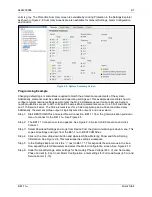
Page 40: ...3 6 9424200996 Controls and Indicators BE1 11m Figure 3 3 Front Panel Display Setup Screen...
Page 54: ...5 6 9424200996 Phase Undervoltage 27P Protection BE1 11m...
Page 56: ...6 2 9424200996 Negative Sequence Voltage 47 Protection BE1 11m...
Page 61: ...9424200996 7 5 BE1 11m Phase Overvoltage 59P Protection Figure 7 3 Overvoltage Settings Screen...
Page 62: ...7 6 9424200996 Phase Overvoltage 59P Protection BE1 11m...
Page 68: ...8 6 9424200996 Auxiliary Overvoltage 59X Protection BE1 11m...
Page 80: ...12 4 9424200996 Instantaneous Overcurrent 50 Protection BE1 11m...
Page 84: ...13 4 9424200996 Breaker Failure 50BF Protection BE1 11m...
Page 92: ...14 8 9424200996 Inverse Overcurrent 51 Protection BE1 11m...
Page 105: ...9424200996 18 3 BE1 11m Power Factor 55 Protection Figure 18 2 Power Factor Settings Screen...
Page 106: ...18 4 9424200996 Power Factor 55 Protection BE1 11m...
Page 110: ...19 4 9424200996 Resistance Temperature Detector 49RTD Protection BE1 11m...
Page 118: ...20 8 9424200996 Thermal Curve 49TC Protection BE1 11m...
Page 122: ...22 2 9424200996 Starts per Time Interval 66 Protection BE1 11m...
Page 124: ...23 2 9424200996 Restart Inhibit Protection BE1 11m...
Page 140: ...28 4 9424200996 Breaker Control Switch 101 BE1 11m...
Page 148: ...29 8 9424200996 Setting Groups BE1 11m...
Page 156: ...30 8 9424200996 Metering BE1 11m Figure 30 11 RTD Meter Screen...
Page 158: ...31 2 9424200996 Digital Points BE1 11m Figure 31 2 Digital Points Monitor Screen...
Page 177: ...9424200996 34 5 BE1 11m Motor Reporting Figure 34 9 Learned Motor Data Screen...
Page 178: ...34 6 9424200996 Motor Reporting BE1 11m...
Page 184: ...35 6 9424200996 Alarms BE1 11m...
Page 186: ...36 2 9424200996 Differential Reporting BE1 11m...
Page 196: ...38 4 9424200996 Demands BE1 11m...
Page 198: ...39 2 9424200996 Load Profile BE1 11m...
Page 208: ...41 6 9424200996 Trip Circuit Monitor 52TCM BE1 11m...
Page 212: ...42 4 9424200996 Fuse Loss 60FL BE1 11m...
Page 218: ...43 6 9424200996 BESTnet Plus BE1 11m Figure 43 8 Power Quality Page...
Page 221: ...9424200996 44 3 BE1 11m Mounting Figure 44 3 Case Side Dimensions...
Page 235: ...9424200996 45 5 BE1 11m Terminals and Connectors Figure 45 7 Example of Reversed CT Polarity...
Page 236: ...45 6 9424200996 Terminals and Connectors BE1 11m...
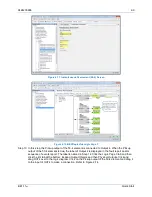
Page 269: ...9424200996 48 15 BE1 11m BESTlogic Plus Figure 48 4 Logic Page 1 for Default Logic...
Page 288: ...49 10 9424200996 Communication BE1 11m Figure 49 14 Modbus Mapping Screen...
Page 306: ...52 4 9424200996 Device Information BE1 11m...
Page 314: ...53 8 9424200996 Configuration BE1 11m Figure 53 3 Display Units Screen...
Page 318: ...54 4 9424200996 Introduction to Testing BE1 11m...
Page 330: ...56 6 9424200996 Commissioning Testing BE1 11m...
Page 336: ...58 4 9424200996 Phase Undervoltage 27P Test BE1 11m...
Page 340: ...59 4 9424200996 Phase Overvoltage 59P Test BE1 11m...
Page 352: ...60 12 9424200996 Auxiliary Overvoltage 59X Test BE1 11m...
Page 360: ...61 8 9424200996 Frequency 81 Test BE1 11m...
Page 364: ...62 4 9424200996 Instantaneous Undercurrent 37 Test BE1 11m...
Page 376: ...63 12 9424200996 Instantaneous Overcurrent 50 Test BE1 11m...
Page 396: ...65 16 9424200996 Inverse Overcurrent 51 Test BE1 11m...
Page 408: ...67 6 9424200996 Power 32 Test BE1 11m...
Page 412: ...68 4 9424200996 Loss of Excitation Reverse Var Based 40Q Test BE1 11m...
Page 426: ...70 10 9424200996 Thermal Curve 49TC Test BE1 11m...
Page 432: ...72 4 9424200996 Starts per Time Interval 66 Test BE1 11m...
Page 436: ...73 4 9424200996 Restart Inhibit Test BE1 11m...
Page 440: ...74 4 9424200996 Virtual Control Switches 43 Test BE1 11m...
Page 450: ...75 10 9424200996 Logic Timers 62 Test BE1 11m...
Page 464: ...79 8 9424200996 Troubleshooting BE1 11m...
Page 480: ...80 16 9424200996 Specifications BE1 11m...
Page 600: ...84 56 9424200996 Settings Calculation Examples BE1 11m Figure 84 70 Logic Page 4 Part 1...
Page 602: ...84 58 9424200996 Settings Calculation Examples BE1 11m...
Page 608: ...85 6 9424200996 BESTCOMSPlus Settings Loader Tool BE1 11m...
Page 609: ......