

9424200996
51-1
BE1-11
m
Timekeeping
51 • Timekeeping
The BE1-11
m
provides a real-time clock with capacitor backup that is capable of operating the clock for
up to 24 hours after power is removed from the BE1-11
m
. As the capacitor nears depletion, an internal
backup battery takes over and maintains timekeeping. The backup battery is standard and will maintain
the clock for more than five years depending on conditions.
The clock is used by the demand reporting function, the fault reporting function, the oscillography
recording function, and the sequence of events recorder function to time-stamp events. The clock function
records the year in two-digit format.
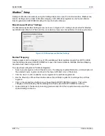
Clock Setup
BESTCOMS
Plus
Navigation Path:
Settings Explorer, General Settings, Clock Setup
HMI Navigation Path:
Settings Explorer, General Settings, Clock Setup
Clock settings are made through the communication ports using BESTCOMS
Plus
®
or through the front-
panel interface. Write access to ports is required to program the clock. An alarm point is provided in the
programmable alarms to detect when the BE1-11
m
has powered up and the clock has not been set.
The clock settings are made through BESTCOMS
Plus
by selecting Clock Setup
under
General Settings
.
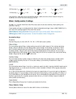
The BESTCOMS
Plus
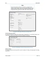
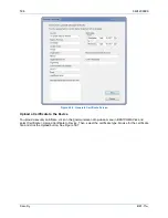
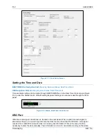
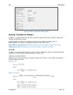
Clock Setup screen is illustrated in Figure 51-1.
The local time zone is configured on this screen. The Time Zone Offset is the local offset to UTC
(Coordinated Universal Time). The Time Zone Offset is required if NTP or IRIG-B is used for time
synchronization or when the Start/End Time Reference is set to UTC (Coordinated Universal Time). The
Start/End Time Reference is set to UTC time if required by local daylight savings time rules. The
Start/End Hour/Minute settings determine the time when the DST will go into effect. The Bias setting is
the amount of time that the clock moves forward or backward. The default settings are configured for the
Central Time Zone in the United States as shown in Figure 51-1. Using these settings, the clock would
move forward 1 hour at 2:00 a.m. on the second Sunday in March and move backward 1 hour at 2:00
a.m. on the first Sunday in November. DST can also be configured for a specific day of the month by
selecting Fixed Dates under DST Configuration.
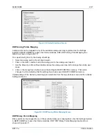
Time Priority Setup
There are three available protocols (NTP, IRIG-B, and DNP), which can be assigned priorities to update
the date and time. Double-click on an available item to move it to the Enabled box. Use the arrow buttons
to set the priority of the selected item. If all three protocols are disabled, the date and time will not be
updated automatically.
The NTP (Network Time Protocol) synchronizes the real-time clock to a network time server when an
Ethernet cable is connected. An address of a valid NTP server must be entered when NTP is selected in
the Time Priority Setup, Enabled box. If using a named server, use the Additional NTP Sources and leave
the NTP Address at 0.0.0.0.
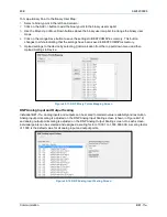
IRIG Decoding
The IRIG Decoding signal defines whether or not to decode the year field in the IRIG signal. Refer to the
manufacturer of your equipment to determine if the year field is being sent to the BE1-11
m
.
Summary of Contents for BE1-11m
Page 8: ...vi 9424200996 Revision History BE1 11m...
Page 12: ...x 9424200996 Contents BE1 11m...
Page 21: ...9424200996 1 9 BE1 11m Introduction Figure 1 1 Style Chart...
Page 22: ...1 10 9424200996 Introduction BE1 11m...
Page 40: ...3 6 9424200996 Controls and Indicators BE1 11m Figure 3 3 Front Panel Display Setup Screen...
Page 54: ...5 6 9424200996 Phase Undervoltage 27P Protection BE1 11m...
Page 56: ...6 2 9424200996 Negative Sequence Voltage 47 Protection BE1 11m...
Page 61: ...9424200996 7 5 BE1 11m Phase Overvoltage 59P Protection Figure 7 3 Overvoltage Settings Screen...
Page 62: ...7 6 9424200996 Phase Overvoltage 59P Protection BE1 11m...
Page 68: ...8 6 9424200996 Auxiliary Overvoltage 59X Protection BE1 11m...
Page 80: ...12 4 9424200996 Instantaneous Overcurrent 50 Protection BE1 11m...
Page 84: ...13 4 9424200996 Breaker Failure 50BF Protection BE1 11m...
Page 92: ...14 8 9424200996 Inverse Overcurrent 51 Protection BE1 11m...
Page 105: ...9424200996 18 3 BE1 11m Power Factor 55 Protection Figure 18 2 Power Factor Settings Screen...
Page 106: ...18 4 9424200996 Power Factor 55 Protection BE1 11m...
Page 110: ...19 4 9424200996 Resistance Temperature Detector 49RTD Protection BE1 11m...
Page 118: ...20 8 9424200996 Thermal Curve 49TC Protection BE1 11m...
Page 122: ...22 2 9424200996 Starts per Time Interval 66 Protection BE1 11m...
Page 124: ...23 2 9424200996 Restart Inhibit Protection BE1 11m...
Page 140: ...28 4 9424200996 Breaker Control Switch 101 BE1 11m...
Page 148: ...29 8 9424200996 Setting Groups BE1 11m...
Page 156: ...30 8 9424200996 Metering BE1 11m Figure 30 11 RTD Meter Screen...
Page 158: ...31 2 9424200996 Digital Points BE1 11m Figure 31 2 Digital Points Monitor Screen...
Page 177: ...9424200996 34 5 BE1 11m Motor Reporting Figure 34 9 Learned Motor Data Screen...
Page 178: ...34 6 9424200996 Motor Reporting BE1 11m...
Page 184: ...35 6 9424200996 Alarms BE1 11m...
Page 186: ...36 2 9424200996 Differential Reporting BE1 11m...
Page 196: ...38 4 9424200996 Demands BE1 11m...
Page 198: ...39 2 9424200996 Load Profile BE1 11m...
Page 208: ...41 6 9424200996 Trip Circuit Monitor 52TCM BE1 11m...
Page 212: ...42 4 9424200996 Fuse Loss 60FL BE1 11m...
Page 218: ...43 6 9424200996 BESTnet Plus BE1 11m Figure 43 8 Power Quality Page...
Page 221: ...9424200996 44 3 BE1 11m Mounting Figure 44 3 Case Side Dimensions...
Page 235: ...9424200996 45 5 BE1 11m Terminals and Connectors Figure 45 7 Example of Reversed CT Polarity...
Page 236: ...45 6 9424200996 Terminals and Connectors BE1 11m...
Page 269: ...9424200996 48 15 BE1 11m BESTlogic Plus Figure 48 4 Logic Page 1 for Default Logic...
Page 288: ...49 10 9424200996 Communication BE1 11m Figure 49 14 Modbus Mapping Screen...
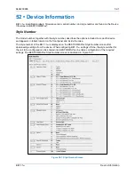
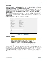
Page 306: ...52 4 9424200996 Device Information BE1 11m...
Page 314: ...53 8 9424200996 Configuration BE1 11m Figure 53 3 Display Units Screen...
Page 318: ...54 4 9424200996 Introduction to Testing BE1 11m...
Page 330: ...56 6 9424200996 Commissioning Testing BE1 11m...
Page 336: ...58 4 9424200996 Phase Undervoltage 27P Test BE1 11m...
Page 340: ...59 4 9424200996 Phase Overvoltage 59P Test BE1 11m...
Page 352: ...60 12 9424200996 Auxiliary Overvoltage 59X Test BE1 11m...
Page 360: ...61 8 9424200996 Frequency 81 Test BE1 11m...
Page 364: ...62 4 9424200996 Instantaneous Undercurrent 37 Test BE1 11m...
Page 376: ...63 12 9424200996 Instantaneous Overcurrent 50 Test BE1 11m...
Page 396: ...65 16 9424200996 Inverse Overcurrent 51 Test BE1 11m...
Page 408: ...67 6 9424200996 Power 32 Test BE1 11m...
Page 412: ...68 4 9424200996 Loss of Excitation Reverse Var Based 40Q Test BE1 11m...
Page 426: ...70 10 9424200996 Thermal Curve 49TC Test BE1 11m...
Page 432: ...72 4 9424200996 Starts per Time Interval 66 Test BE1 11m...
Page 436: ...73 4 9424200996 Restart Inhibit Test BE1 11m...
Page 440: ...74 4 9424200996 Virtual Control Switches 43 Test BE1 11m...
Page 450: ...75 10 9424200996 Logic Timers 62 Test BE1 11m...
Page 464: ...79 8 9424200996 Troubleshooting BE1 11m...
Page 480: ...80 16 9424200996 Specifications BE1 11m...
Page 600: ...84 56 9424200996 Settings Calculation Examples BE1 11m Figure 84 70 Logic Page 4 Part 1...
Page 602: ...84 58 9424200996 Settings Calculation Examples BE1 11m...
Page 608: ...85 6 9424200996 BESTCOMSPlus Settings Loader Tool BE1 11m...
Page 609: ......