

9424200996
80-11
BE1-11
m
Specifications
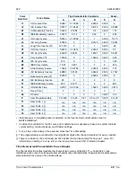
Input Burden
Burden values shown in Table 80-2 assume nominal value of input voltage applied.
Table 80-2. Contact-Sensing Input Burden
Style Option
Nominal Input Voltage
Burden
Jumper Installed
(Low Position)
Jumper Not Installed
(High Position)
Mxx1xxxxxxxxxx
48 Vdc or 125 Vac/dc
22 k
Ω
53 k
Ω
Mxx2xxxxxxxxxx
125/250 Vac/dc
66 k
Ω
123 k
Ω
Mxx3xxxxxxxxxx
24 Vdc
n/a
6 k
Ω
Recognition Time
Programmable ........................................................... 4 to 255 ms
Note
All timing specifications are for the worst-case response. This includes
output contact operate times and standard BESTlogic
Plus
operation
timing but excludes input debounce timing and nonstandard logic
configurations. If a nonstandard logic scheme involves feedback, then
one or more BESTlogic
Plus
update rate delays must be included to
calculate the worst-case delay. An example of feedback is logic
outputs driving logic inputs. For more information, see
BESTlogicPlus
.
Terminals
IN1 ............................................................................. B1, B2
IN2 ............................................................................. B3, B4
IN3 ............................................................................. B5, B6
IN4 ............................................................................. B7, B8
IN5 ............................................................................. E1, E2
IN6 ............................................................................. E3, E4
IN7 ............................................................................. E5, E6
IN8 (Optional) ............................................................ E7, E8
IN9 (Optional) ............................................................ E9, E10
IN10 (Optional) .......................................................... E11, E12
IRIG Interface
Standard ........................................... 200-98, Format B002, and 200-04, Format B006
Input Signal ...................................... Demodulated (dc level-shifted signal)
Logic High Level ............................... 3.5 Vdc, minimum
Logic Low Level ............................... 0.5 Vdc, maximum
Input Voltage Range ........................ –10 to +10 Vdc
Input Resistance .............................. Nonlinear, approximately 4 k
Ω
at 3.5 Vdc,
3 k
Ω
at 20 Vdc
Response Time ................................ <1 cycle
Terminals.......................................... A1, A2
Real-Time Clock
Clock has leap year and selectable daylight saving time correction. Backup capacitor and standard
backup battery sustain timekeeping during losses of BE1-11
m
operating power.
Resolution ................................................................. 1 s
Accuracy....................................................................
±
1.73 s/d at 77°F (25°C)
Summary of Contents for BE1-11m
Page 8: ...vi 9424200996 Revision History BE1 11m...
Page 12: ...x 9424200996 Contents BE1 11m...
Page 21: ...9424200996 1 9 BE1 11m Introduction Figure 1 1 Style Chart...
Page 22: ...1 10 9424200996 Introduction BE1 11m...
Page 40: ...3 6 9424200996 Controls and Indicators BE1 11m Figure 3 3 Front Panel Display Setup Screen...
Page 54: ...5 6 9424200996 Phase Undervoltage 27P Protection BE1 11m...
Page 56: ...6 2 9424200996 Negative Sequence Voltage 47 Protection BE1 11m...
Page 61: ...9424200996 7 5 BE1 11m Phase Overvoltage 59P Protection Figure 7 3 Overvoltage Settings Screen...
Page 62: ...7 6 9424200996 Phase Overvoltage 59P Protection BE1 11m...
Page 68: ...8 6 9424200996 Auxiliary Overvoltage 59X Protection BE1 11m...
Page 80: ...12 4 9424200996 Instantaneous Overcurrent 50 Protection BE1 11m...
Page 84: ...13 4 9424200996 Breaker Failure 50BF Protection BE1 11m...
Page 92: ...14 8 9424200996 Inverse Overcurrent 51 Protection BE1 11m...
Page 105: ...9424200996 18 3 BE1 11m Power Factor 55 Protection Figure 18 2 Power Factor Settings Screen...
Page 106: ...18 4 9424200996 Power Factor 55 Protection BE1 11m...
Page 110: ...19 4 9424200996 Resistance Temperature Detector 49RTD Protection BE1 11m...
Page 118: ...20 8 9424200996 Thermal Curve 49TC Protection BE1 11m...
Page 122: ...22 2 9424200996 Starts per Time Interval 66 Protection BE1 11m...
Page 124: ...23 2 9424200996 Restart Inhibit Protection BE1 11m...
Page 140: ...28 4 9424200996 Breaker Control Switch 101 BE1 11m...
Page 148: ...29 8 9424200996 Setting Groups BE1 11m...
Page 156: ...30 8 9424200996 Metering BE1 11m Figure 30 11 RTD Meter Screen...
Page 158: ...31 2 9424200996 Digital Points BE1 11m Figure 31 2 Digital Points Monitor Screen...
Page 177: ...9424200996 34 5 BE1 11m Motor Reporting Figure 34 9 Learned Motor Data Screen...
Page 178: ...34 6 9424200996 Motor Reporting BE1 11m...
Page 184: ...35 6 9424200996 Alarms BE1 11m...
Page 186: ...36 2 9424200996 Differential Reporting BE1 11m...
Page 196: ...38 4 9424200996 Demands BE1 11m...
Page 198: ...39 2 9424200996 Load Profile BE1 11m...
Page 208: ...41 6 9424200996 Trip Circuit Monitor 52TCM BE1 11m...
Page 212: ...42 4 9424200996 Fuse Loss 60FL BE1 11m...
Page 218: ...43 6 9424200996 BESTnet Plus BE1 11m Figure 43 8 Power Quality Page...
Page 221: ...9424200996 44 3 BE1 11m Mounting Figure 44 3 Case Side Dimensions...
Page 235: ...9424200996 45 5 BE1 11m Terminals and Connectors Figure 45 7 Example of Reversed CT Polarity...
Page 236: ...45 6 9424200996 Terminals and Connectors BE1 11m...
Page 269: ...9424200996 48 15 BE1 11m BESTlogic Plus Figure 48 4 Logic Page 1 for Default Logic...
Page 288: ...49 10 9424200996 Communication BE1 11m Figure 49 14 Modbus Mapping Screen...
Page 306: ...52 4 9424200996 Device Information BE1 11m...
Page 314: ...53 8 9424200996 Configuration BE1 11m Figure 53 3 Display Units Screen...
Page 318: ...54 4 9424200996 Introduction to Testing BE1 11m...
Page 330: ...56 6 9424200996 Commissioning Testing BE1 11m...
Page 336: ...58 4 9424200996 Phase Undervoltage 27P Test BE1 11m...
Page 340: ...59 4 9424200996 Phase Overvoltage 59P Test BE1 11m...
Page 352: ...60 12 9424200996 Auxiliary Overvoltage 59X Test BE1 11m...
Page 360: ...61 8 9424200996 Frequency 81 Test BE1 11m...
Page 364: ...62 4 9424200996 Instantaneous Undercurrent 37 Test BE1 11m...
Page 376: ...63 12 9424200996 Instantaneous Overcurrent 50 Test BE1 11m...
Page 396: ...65 16 9424200996 Inverse Overcurrent 51 Test BE1 11m...
Page 408: ...67 6 9424200996 Power 32 Test BE1 11m...
Page 412: ...68 4 9424200996 Loss of Excitation Reverse Var Based 40Q Test BE1 11m...
Page 426: ...70 10 9424200996 Thermal Curve 49TC Test BE1 11m...
Page 432: ...72 4 9424200996 Starts per Time Interval 66 Test BE1 11m...
Page 436: ...73 4 9424200996 Restart Inhibit Test BE1 11m...
Page 440: ...74 4 9424200996 Virtual Control Switches 43 Test BE1 11m...
Page 450: ...75 10 9424200996 Logic Timers 62 Test BE1 11m...
Page 464: ...79 8 9424200996 Troubleshooting BE1 11m...
Page 480: ...80 16 9424200996 Specifications BE1 11m...
Page 600: ...84 56 9424200996 Settings Calculation Examples BE1 11m Figure 84 70 Logic Page 4 Part 1...
Page 602: ...84 58 9424200996 Settings Calculation Examples BE1 11m...
Page 608: ...85 6 9424200996 BESTCOMSPlus Settings Loader Tool BE1 11m...
Page 609: ......