


9424200996
26-3
BE1-11
m
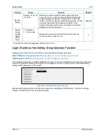
Logic Timers (62)
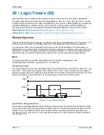
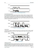
time delay for the output to change to false if it is presently true and the initiate input becomes false and
stays false.
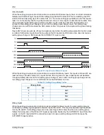
In the example shown in Figure 26-5, T2 is set to half of the T1 setting. The initiate input becomes true
and the timer starts integrating toward pickup. Prior to timing out, the Initiate input toggles to false and the
timer starts resetting at twice the rate as it was integrating toward time out. It stays false long enough for
the integrating timer to reset completely but then toggles back to true and stays true for the entire duration
of time T1. At that point, the timer’s output is toggled to true. Then later, the initiate Input becomes false
and stays false for the duration of T2. At that point, the output of the timer is toggled to false.
This type of timer is useful in applications where a monitored signal might be hovering at its threshold
between on and off. For example, it is desired to take some action when current is above a certain level
for a certain period. An instantaneous overcurrent (50) element could be used to monitor the current level.
Thus, if the current level is near the threshold so that the Initiate input toggles between true and false
from time to time, the function will still time out as long as the time that it is true is longer than the time
that it is false. With a simple pickup/dropout timer, the timing function would reset to zero and start over
each time the Initiate input became false.
Figure 26-5. Integrating Timer Mode
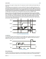
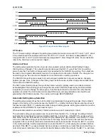
Latched Mode
A one shot timer starts its timing sequence when the Initiate input changes from false to true. The timer
will operate for Delay Time (T1) and then the output will latch true. Additional Initiate input changes of
state are ignored. Time (T2) is ignored. Refer to Figure 26-6.
Figure 26-6. Latched Mode
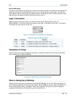
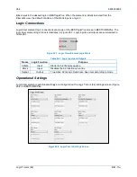
Element Blocking
The Block input provides logic-supervision control of the element. When true, the Block input disables the
element by forcing the element output to logic 0 and resetting the element timer. Connect the element
P0
03
5-
34
02
-2
7-
06
62-x
Block
Initiate
100%
0%
Timer
P
00
35
-3
5
02
-2
7-
06
Block
Initiate
62-x
Summary of Contents for BE1-11m
Page 8: ...vi 9424200996 Revision History BE1 11m...
Page 12: ...x 9424200996 Contents BE1 11m...
Page 21: ...9424200996 1 9 BE1 11m Introduction Figure 1 1 Style Chart...
Page 22: ...1 10 9424200996 Introduction BE1 11m...
Page 40: ...3 6 9424200996 Controls and Indicators BE1 11m Figure 3 3 Front Panel Display Setup Screen...
Page 54: ...5 6 9424200996 Phase Undervoltage 27P Protection BE1 11m...
Page 56: ...6 2 9424200996 Negative Sequence Voltage 47 Protection BE1 11m...
Page 61: ...9424200996 7 5 BE1 11m Phase Overvoltage 59P Protection Figure 7 3 Overvoltage Settings Screen...
Page 62: ...7 6 9424200996 Phase Overvoltage 59P Protection BE1 11m...
Page 68: ...8 6 9424200996 Auxiliary Overvoltage 59X Protection BE1 11m...
Page 80: ...12 4 9424200996 Instantaneous Overcurrent 50 Protection BE1 11m...
Page 84: ...13 4 9424200996 Breaker Failure 50BF Protection BE1 11m...
Page 92: ...14 8 9424200996 Inverse Overcurrent 51 Protection BE1 11m...
Page 105: ...9424200996 18 3 BE1 11m Power Factor 55 Protection Figure 18 2 Power Factor Settings Screen...
Page 106: ...18 4 9424200996 Power Factor 55 Protection BE1 11m...
Page 110: ...19 4 9424200996 Resistance Temperature Detector 49RTD Protection BE1 11m...
Page 118: ...20 8 9424200996 Thermal Curve 49TC Protection BE1 11m...
Page 122: ...22 2 9424200996 Starts per Time Interval 66 Protection BE1 11m...
Page 124: ...23 2 9424200996 Restart Inhibit Protection BE1 11m...
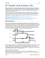
Page 140: ...28 4 9424200996 Breaker Control Switch 101 BE1 11m...
Page 148: ...29 8 9424200996 Setting Groups BE1 11m...
Page 156: ...30 8 9424200996 Metering BE1 11m Figure 30 11 RTD Meter Screen...
Page 158: ...31 2 9424200996 Digital Points BE1 11m Figure 31 2 Digital Points Monitor Screen...
Page 177: ...9424200996 34 5 BE1 11m Motor Reporting Figure 34 9 Learned Motor Data Screen...
Page 178: ...34 6 9424200996 Motor Reporting BE1 11m...
Page 184: ...35 6 9424200996 Alarms BE1 11m...
Page 186: ...36 2 9424200996 Differential Reporting BE1 11m...
Page 196: ...38 4 9424200996 Demands BE1 11m...
Page 198: ...39 2 9424200996 Load Profile BE1 11m...
Page 208: ...41 6 9424200996 Trip Circuit Monitor 52TCM BE1 11m...
Page 212: ...42 4 9424200996 Fuse Loss 60FL BE1 11m...
Page 218: ...43 6 9424200996 BESTnet Plus BE1 11m Figure 43 8 Power Quality Page...
Page 221: ...9424200996 44 3 BE1 11m Mounting Figure 44 3 Case Side Dimensions...
Page 235: ...9424200996 45 5 BE1 11m Terminals and Connectors Figure 45 7 Example of Reversed CT Polarity...
Page 236: ...45 6 9424200996 Terminals and Connectors BE1 11m...
Page 269: ...9424200996 48 15 BE1 11m BESTlogic Plus Figure 48 4 Logic Page 1 for Default Logic...
Page 288: ...49 10 9424200996 Communication BE1 11m Figure 49 14 Modbus Mapping Screen...
Page 306: ...52 4 9424200996 Device Information BE1 11m...
Page 314: ...53 8 9424200996 Configuration BE1 11m Figure 53 3 Display Units Screen...
Page 318: ...54 4 9424200996 Introduction to Testing BE1 11m...
Page 330: ...56 6 9424200996 Commissioning Testing BE1 11m...
Page 336: ...58 4 9424200996 Phase Undervoltage 27P Test BE1 11m...
Page 340: ...59 4 9424200996 Phase Overvoltage 59P Test BE1 11m...
Page 352: ...60 12 9424200996 Auxiliary Overvoltage 59X Test BE1 11m...
Page 360: ...61 8 9424200996 Frequency 81 Test BE1 11m...
Page 364: ...62 4 9424200996 Instantaneous Undercurrent 37 Test BE1 11m...
Page 376: ...63 12 9424200996 Instantaneous Overcurrent 50 Test BE1 11m...
Page 396: ...65 16 9424200996 Inverse Overcurrent 51 Test BE1 11m...
Page 408: ...67 6 9424200996 Power 32 Test BE1 11m...
Page 412: ...68 4 9424200996 Loss of Excitation Reverse Var Based 40Q Test BE1 11m...
Page 426: ...70 10 9424200996 Thermal Curve 49TC Test BE1 11m...
Page 432: ...72 4 9424200996 Starts per Time Interval 66 Test BE1 11m...
Page 436: ...73 4 9424200996 Restart Inhibit Test BE1 11m...
Page 440: ...74 4 9424200996 Virtual Control Switches 43 Test BE1 11m...
Page 450: ...75 10 9424200996 Logic Timers 62 Test BE1 11m...
Page 464: ...79 8 9424200996 Troubleshooting BE1 11m...
Page 480: ...80 16 9424200996 Specifications BE1 11m...
Page 600: ...84 56 9424200996 Settings Calculation Examples BE1 11m Figure 84 70 Logic Page 4 Part 1...
Page 602: ...84 58 9424200996 Settings Calculation Examples BE1 11m...
Page 608: ...85 6 9424200996 BESTCOMSPlus Settings Loader Tool BE1 11m...
Page 609: ......