


53-2
9424200996
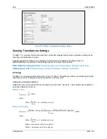
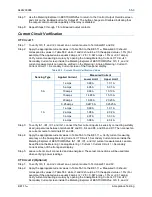
Configuration
BE1-11
m
VT Connections
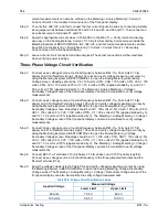
When four-wire VT connections are used, the BE1-11
m
measures the three-phase to neutral voltages and
calculates the phase voltage quantities. Overvoltage and undervoltage functions (27/59) can be set to
operate on either the phase-to-neutral (PN) or phase-to-phase (PP) quantities. Three-wire VT
connections limit 27/59 operation to PP quantities. When single-phase VT connections are used, the
27/59 elements operate as appropriate for the single-phase voltage applied.
Neutral-Shift Voltage
When four-wire VT connections are used, the BE1-11
m
calculates the neutral-shift voltage (3V0). Neutral-
shift voltage measurement is not available when single-phase or three-wire VT connections are used. The
59X can be set to monitor the neutral-shift voltage.
Negative-Sequence Voltage
Negative-sequence voltage (V2) is calculated from the fundamental component of the three-phase
voltage inputs. It is available only on three-phase, three-wire, or three-phase, four-wire systems. V2 is
calibrated to the phase-to-neutral base. Negative-sequence measurements accommodate either an ABC
or ACB phase-sequence.
Positive-Sequence Voltage
Positive-sequence voltage (V1) is calculated from the fundamental component of the three-phase voltage
inputs. It is available only on three-phase, three-wire, or three-phase, four-wire systems. V1 is calibrated
to the phase-to-neutral base. Positive-sequence measurements can accommodate either ABC or ACB
phase-sequence.
Frequency Measurement
Power system frequency is monitored on the A-phase voltage input or the AB voltage input when in three-
wire mode. When the applied voltage is greater than 10 volts, the BE1-11
m
measures the frequency. The
measured frequency is used by the 81 function and applies to all measurements and calculations.
Frequency Compensation
After measuring the frequency, the BE1-11
m
varies the sampling rate to maintain 32 samples per cycle
over a frequency of 10 to 125 hertz. If the voltage is too low for accurate frequency measurement or if the
measured frequency is out of range, the analog-to-digital converter (ADC) defaults to a sampling rate
appropriate for the BE1-11
m
nominal frequency setting. The sampling rate is adjusted every 50
milliseconds (3 cycles).
Nominal Frequency
Nominal frequency (F
nom
) can be set for 25-, 50-, 60-, or 100-hertz power systems. When the voltage and
current are too low for reliable frequency measurement, the ADC sample rate defaults to operation at the
nominal frequency setting.
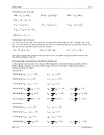
Power Measurement
The measured fundamental component of current and voltage as described previously in this chapter is
used to calculate the power per the equations following:
Summary of Contents for BE1-11m
Page 8: ...vi 9424200996 Revision History BE1 11m...
Page 12: ...x 9424200996 Contents BE1 11m...
Page 21: ...9424200996 1 9 BE1 11m Introduction Figure 1 1 Style Chart...
Page 22: ...1 10 9424200996 Introduction BE1 11m...
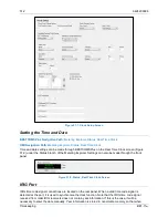
Page 40: ...3 6 9424200996 Controls and Indicators BE1 11m Figure 3 3 Front Panel Display Setup Screen...
Page 54: ...5 6 9424200996 Phase Undervoltage 27P Protection BE1 11m...
Page 56: ...6 2 9424200996 Negative Sequence Voltage 47 Protection BE1 11m...
Page 61: ...9424200996 7 5 BE1 11m Phase Overvoltage 59P Protection Figure 7 3 Overvoltage Settings Screen...
Page 62: ...7 6 9424200996 Phase Overvoltage 59P Protection BE1 11m...
Page 68: ...8 6 9424200996 Auxiliary Overvoltage 59X Protection BE1 11m...
Page 80: ...12 4 9424200996 Instantaneous Overcurrent 50 Protection BE1 11m...
Page 84: ...13 4 9424200996 Breaker Failure 50BF Protection BE1 11m...
Page 92: ...14 8 9424200996 Inverse Overcurrent 51 Protection BE1 11m...
Page 105: ...9424200996 18 3 BE1 11m Power Factor 55 Protection Figure 18 2 Power Factor Settings Screen...
Page 106: ...18 4 9424200996 Power Factor 55 Protection BE1 11m...
Page 110: ...19 4 9424200996 Resistance Temperature Detector 49RTD Protection BE1 11m...
Page 118: ...20 8 9424200996 Thermal Curve 49TC Protection BE1 11m...
Page 122: ...22 2 9424200996 Starts per Time Interval 66 Protection BE1 11m...
Page 124: ...23 2 9424200996 Restart Inhibit Protection BE1 11m...
Page 140: ...28 4 9424200996 Breaker Control Switch 101 BE1 11m...
Page 148: ...29 8 9424200996 Setting Groups BE1 11m...
Page 156: ...30 8 9424200996 Metering BE1 11m Figure 30 11 RTD Meter Screen...
Page 158: ...31 2 9424200996 Digital Points BE1 11m Figure 31 2 Digital Points Monitor Screen...
Page 177: ...9424200996 34 5 BE1 11m Motor Reporting Figure 34 9 Learned Motor Data Screen...
Page 178: ...34 6 9424200996 Motor Reporting BE1 11m...
Page 184: ...35 6 9424200996 Alarms BE1 11m...
Page 186: ...36 2 9424200996 Differential Reporting BE1 11m...
Page 196: ...38 4 9424200996 Demands BE1 11m...
Page 198: ...39 2 9424200996 Load Profile BE1 11m...
Page 208: ...41 6 9424200996 Trip Circuit Monitor 52TCM BE1 11m...
Page 212: ...42 4 9424200996 Fuse Loss 60FL BE1 11m...
Page 218: ...43 6 9424200996 BESTnet Plus BE1 11m Figure 43 8 Power Quality Page...
Page 221: ...9424200996 44 3 BE1 11m Mounting Figure 44 3 Case Side Dimensions...
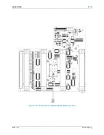
Page 235: ...9424200996 45 5 BE1 11m Terminals and Connectors Figure 45 7 Example of Reversed CT Polarity...
Page 236: ...45 6 9424200996 Terminals and Connectors BE1 11m...
Page 269: ...9424200996 48 15 BE1 11m BESTlogic Plus Figure 48 4 Logic Page 1 for Default Logic...
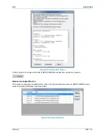
Page 288: ...49 10 9424200996 Communication BE1 11m Figure 49 14 Modbus Mapping Screen...
Page 306: ...52 4 9424200996 Device Information BE1 11m...
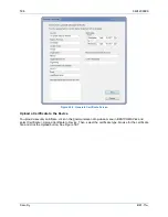
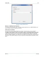
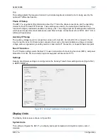
Page 314: ...53 8 9424200996 Configuration BE1 11m Figure 53 3 Display Units Screen...
Page 318: ...54 4 9424200996 Introduction to Testing BE1 11m...
Page 330: ...56 6 9424200996 Commissioning Testing BE1 11m...
Page 336: ...58 4 9424200996 Phase Undervoltage 27P Test BE1 11m...
Page 340: ...59 4 9424200996 Phase Overvoltage 59P Test BE1 11m...
Page 352: ...60 12 9424200996 Auxiliary Overvoltage 59X Test BE1 11m...
Page 360: ...61 8 9424200996 Frequency 81 Test BE1 11m...
Page 364: ...62 4 9424200996 Instantaneous Undercurrent 37 Test BE1 11m...
Page 376: ...63 12 9424200996 Instantaneous Overcurrent 50 Test BE1 11m...
Page 396: ...65 16 9424200996 Inverse Overcurrent 51 Test BE1 11m...
Page 408: ...67 6 9424200996 Power 32 Test BE1 11m...
Page 412: ...68 4 9424200996 Loss of Excitation Reverse Var Based 40Q Test BE1 11m...
Page 426: ...70 10 9424200996 Thermal Curve 49TC Test BE1 11m...
Page 432: ...72 4 9424200996 Starts per Time Interval 66 Test BE1 11m...
Page 436: ...73 4 9424200996 Restart Inhibit Test BE1 11m...
Page 440: ...74 4 9424200996 Virtual Control Switches 43 Test BE1 11m...
Page 450: ...75 10 9424200996 Logic Timers 62 Test BE1 11m...
Page 464: ...79 8 9424200996 Troubleshooting BE1 11m...
Page 480: ...80 16 9424200996 Specifications BE1 11m...
Page 600: ...84 56 9424200996 Settings Calculation Examples BE1 11m Figure 84 70 Logic Page 4 Part 1...
Page 602: ...84 58 9424200996 Settings Calculation Examples BE1 11m...
Page 608: ...85 6 9424200996 BESTCOMSPlus Settings Loader Tool BE1 11m...
Page 609: ......