


9424200996
69-3
BE1-11
m
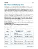
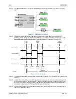
Power Factor (55) Test
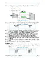
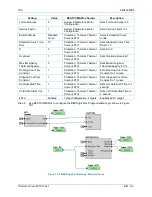
Step 3: Connect and apply 5A
∠
0
°
to terminals D1 (A-phase polarity) and D2 (A-phase non-polarity) and
a three-phase 69.28 V phase-neutral voltage source to terminals C13 (A-phase), C14 (B-
phase), C15 (C-phase), and C16 (Neutral).
Step 4: Rotate the IA angle in the leading or lagging direction until a pickup occurs. This should occur at
60,000ms
±
300ms. Decrease the IA angle until OUT1 opens. Reset the target. Measure the
time delay and record the result.
Step 5: Repeat step 4 for the time delays in the second and third rows of Table 2. Record the results.
Timing accuracy is
±
0.5% or 2 cycles, whichever is greater.
Step 6: (Optional.) Repeat steps 1 through 5 for the B-phase and C-phase voltage inputs taking into
consideration the different current angles. Note: Be sure to enable proper target for each phase
being tested.
Step 7: (Optional.) Repeat steps 1 through 6 for settings group 1, 2, and 3.
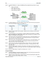
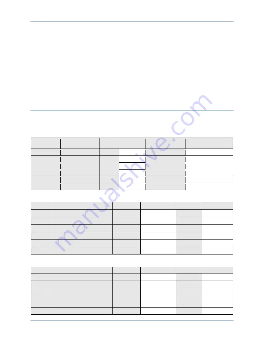
Functional Test Report
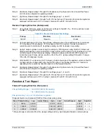
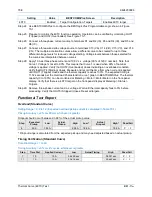
Pickup Verification Table 2 Row 1
Pickup Setting Range = 0.05 to 0.99 leading/lagging
Pickup Accuracy =
±
0.01
Step
Pickup Setting
Low
Actual
Pickup
High
Pass/Fail
6-IA
+60
°
(0.5 leading)
59.34
°
60.66
°
P / F
7-IA
–
60
°
(0.5 lagging)
–
59.34
°
–
60.66
°
P / F
6-IB
+300
°
(0.5 leading)
299.34
°
300.66
°
P / F
7-IB
+180
°
(0.5 lagging)
179.34
°
180.66
°
P / F
6-IC
+180
°
(0.5 leading)
179.34
°
180.66
°
P / F
7-IC
+60
°
(0.5 lagging)
59.34
°
60.66
°
P / F
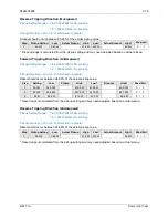
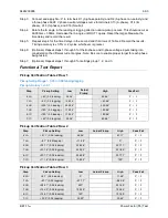
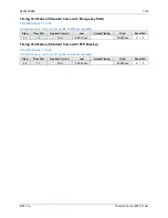
Pickup Verification Table 2 Row 2
Step
Pickup Setting
Low
Actual Pickup
High
Pass/Fail
6-IA
+87.1
°
(0.05 leading)
86.56
°
87.71
°
P / F
7-IA
–
8.1
°
(0.99 lagging)
–
11.48
°
0
°
P / F
6-IB
+327.1
°
(0.05 leading)
326.56
°
327.71
°
P / F
7-IB
+231.8
°
(0.99 lagging)
228.52
°
231.89
°
P / F
6-IC
+207.1
°
(0.05 leading)
206.56
°
207.71
°
P / F
7-IC
+111.8
°
(0.99 lagging)
108.52
°
120
°
P / F
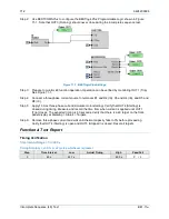
Pickup Verification Table 2 Row 3
Step
Pickup Setting
Low
Actual Pickup
High
Pass/Fail
6-IA
+8.1
°
(0.99 leading)
0
°
11.48
°
P / F
7-IA
–
87.1
°
(0.05 lagging)
–
87.71
°
–
86.56
°
P / F
6-IB
+248.1
°
(0.99 leading)
240
°
251.48
°
P / F
7-IB
+152.9
°
(0.05 lagging)
152.29
°
153.44
°
P / F
6-IC
+128.1
°
(0.99 leading)
120
°
131.48
°
P / F
7-IC
+32.9
°
(0.05 lagging)
32.29
°
33.44
°
P / F
Summary of Contents for BE1-11m
Page 8: ...vi 9424200996 Revision History BE1 11m...
Page 12: ...x 9424200996 Contents BE1 11m...
Page 21: ...9424200996 1 9 BE1 11m Introduction Figure 1 1 Style Chart...
Page 22: ...1 10 9424200996 Introduction BE1 11m...
Page 40: ...3 6 9424200996 Controls and Indicators BE1 11m Figure 3 3 Front Panel Display Setup Screen...
Page 54: ...5 6 9424200996 Phase Undervoltage 27P Protection BE1 11m...
Page 56: ...6 2 9424200996 Negative Sequence Voltage 47 Protection BE1 11m...
Page 61: ...9424200996 7 5 BE1 11m Phase Overvoltage 59P Protection Figure 7 3 Overvoltage Settings Screen...
Page 62: ...7 6 9424200996 Phase Overvoltage 59P Protection BE1 11m...
Page 68: ...8 6 9424200996 Auxiliary Overvoltage 59X Protection BE1 11m...
Page 80: ...12 4 9424200996 Instantaneous Overcurrent 50 Protection BE1 11m...
Page 84: ...13 4 9424200996 Breaker Failure 50BF Protection BE1 11m...
Page 92: ...14 8 9424200996 Inverse Overcurrent 51 Protection BE1 11m...
Page 105: ...9424200996 18 3 BE1 11m Power Factor 55 Protection Figure 18 2 Power Factor Settings Screen...
Page 106: ...18 4 9424200996 Power Factor 55 Protection BE1 11m...
Page 110: ...19 4 9424200996 Resistance Temperature Detector 49RTD Protection BE1 11m...
Page 118: ...20 8 9424200996 Thermal Curve 49TC Protection BE1 11m...
Page 122: ...22 2 9424200996 Starts per Time Interval 66 Protection BE1 11m...
Page 124: ...23 2 9424200996 Restart Inhibit Protection BE1 11m...
Page 140: ...28 4 9424200996 Breaker Control Switch 101 BE1 11m...
Page 148: ...29 8 9424200996 Setting Groups BE1 11m...
Page 156: ...30 8 9424200996 Metering BE1 11m Figure 30 11 RTD Meter Screen...
Page 158: ...31 2 9424200996 Digital Points BE1 11m Figure 31 2 Digital Points Monitor Screen...
Page 177: ...9424200996 34 5 BE1 11m Motor Reporting Figure 34 9 Learned Motor Data Screen...
Page 178: ...34 6 9424200996 Motor Reporting BE1 11m...
Page 184: ...35 6 9424200996 Alarms BE1 11m...
Page 186: ...36 2 9424200996 Differential Reporting BE1 11m...
Page 196: ...38 4 9424200996 Demands BE1 11m...
Page 198: ...39 2 9424200996 Load Profile BE1 11m...
Page 208: ...41 6 9424200996 Trip Circuit Monitor 52TCM BE1 11m...
Page 212: ...42 4 9424200996 Fuse Loss 60FL BE1 11m...
Page 218: ...43 6 9424200996 BESTnet Plus BE1 11m Figure 43 8 Power Quality Page...
Page 221: ...9424200996 44 3 BE1 11m Mounting Figure 44 3 Case Side Dimensions...
Page 235: ...9424200996 45 5 BE1 11m Terminals and Connectors Figure 45 7 Example of Reversed CT Polarity...
Page 236: ...45 6 9424200996 Terminals and Connectors BE1 11m...
Page 269: ...9424200996 48 15 BE1 11m BESTlogic Plus Figure 48 4 Logic Page 1 for Default Logic...
Page 288: ...49 10 9424200996 Communication BE1 11m Figure 49 14 Modbus Mapping Screen...
Page 306: ...52 4 9424200996 Device Information BE1 11m...
Page 314: ...53 8 9424200996 Configuration BE1 11m Figure 53 3 Display Units Screen...
Page 318: ...54 4 9424200996 Introduction to Testing BE1 11m...
Page 330: ...56 6 9424200996 Commissioning Testing BE1 11m...
Page 336: ...58 4 9424200996 Phase Undervoltage 27P Test BE1 11m...
Page 340: ...59 4 9424200996 Phase Overvoltage 59P Test BE1 11m...
Page 352: ...60 12 9424200996 Auxiliary Overvoltage 59X Test BE1 11m...
Page 360: ...61 8 9424200996 Frequency 81 Test BE1 11m...
Page 364: ...62 4 9424200996 Instantaneous Undercurrent 37 Test BE1 11m...
Page 376: ...63 12 9424200996 Instantaneous Overcurrent 50 Test BE1 11m...
Page 396: ...65 16 9424200996 Inverse Overcurrent 51 Test BE1 11m...
Page 408: ...67 6 9424200996 Power 32 Test BE1 11m...
Page 412: ...68 4 9424200996 Loss of Excitation Reverse Var Based 40Q Test BE1 11m...
Page 426: ...70 10 9424200996 Thermal Curve 49TC Test BE1 11m...
Page 432: ...72 4 9424200996 Starts per Time Interval 66 Test BE1 11m...
Page 436: ...73 4 9424200996 Restart Inhibit Test BE1 11m...
Page 440: ...74 4 9424200996 Virtual Control Switches 43 Test BE1 11m...
Page 450: ...75 10 9424200996 Logic Timers 62 Test BE1 11m...
Page 464: ...79 8 9424200996 Troubleshooting BE1 11m...
Page 480: ...80 16 9424200996 Specifications BE1 11m...
Page 600: ...84 56 9424200996 Settings Calculation Examples BE1 11m Figure 84 70 Logic Page 4 Part 1...
Page 602: ...84 58 9424200996 Settings Calculation Examples BE1 11m...
Page 608: ...85 6 9424200996 BESTCOMSPlus Settings Loader Tool BE1 11m...
Page 609: ......