


9424200996
19-1
BE1-11
m
Resistance Temperature Detector (49RTD) Protection
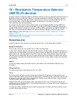
19 • Resistance Temperature Detector
(49RTD) Protection
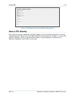
Fourteen resistance temperature detector (49RTD) elements provide over/undertemperature protection in
applications when a remote RTD module is connected via Ethernet or RS-485. There are 12 physical
RTD sensors per RTD module. Each element can be set to monitor a single physical RTD sensor or a
group of them. Refer to the
RTD Module
chapter for information on mounting, connections,
communication setup, and specifications.
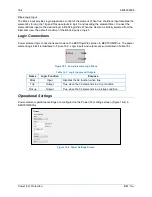
The fourteen, identical remote RTD protection elements are designated 49RTD-1 through 49RTD-14.
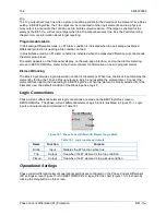
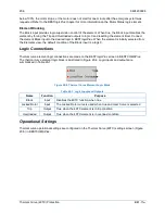
Element logic connections are made on the BESTlogic
™
Plus
screen in BESTCOMS
Plus
®
and element
operational settings are configured on the Remote RTD (49RTD) settings screen in BESTCOMS
Plus
. A
summary of the logic inputs and outputs and operational settings appears at the end of this section.
BESTCOMS
Plus
Navigation Path:
Settings Explorer, Protection, Thermal, Resistance Temperature
Detector (49RTD)
HMI Navigation Path:
Settings Explorer, Protection, Settings Group x (where x = 0 to 3), Thermal
Protection, Resistance Temp 49RTD
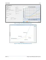
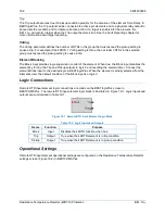
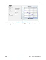
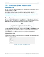
Element Operation
Each RTD input can be configured to protect against high, low, or both temperature conditions.
Modes of Protection
Three modes of protection are available: Over, Under, and Over/Under.
In Over mode, if the temperature of the RTD is above the Over Pickup setting, the element will pick up. In
Under mode, if the temperature of the RTD is below the Under Pickup setting, the element will pick up. In
Over/Under mode, if the temperature of the RTD is above the Over Pickup setting or below the Under
Pickup setting, the element will pick up. The element will remain in the picked-up condition and continue
timing towards a trip unless the temperature falls below the Over Pickup setting or rises above the Under
Pickup setting.
Source
The Source setting selects which RTD input to monitor. Refer to the
RTD Module
chapter for more
information.
Pickup and Trip
The Pickup output occurs first, followed by the Trip output.
Pickup
The Pickup output becomes true when the measured remote RTD input value increases above (Over
mode) or decreases below (Under mode) the pickup setting. In BESTlogic
Plus
, the Pickup output can be
connected to other logic elements to annunciate the condition, control other elements in logic, and start
the fault recorder (logic element FAULTTRIG).
Assertion of the Pickup output initiates a timer that begins timing to a trip. The duration of the timer is
established by the Time Delay setting. A Time Delay setting of zero (0) makes the element instantaneous
with no intentional time delay.
If the pickup condition subsides before the element delay expires, the timer and Pickup output are reset
and no corrective action is taken.
Summary of Contents for BE1-11m
Page 8: ...vi 9424200996 Revision History BE1 11m...
Page 12: ...x 9424200996 Contents BE1 11m...
Page 21: ...9424200996 1 9 BE1 11m Introduction Figure 1 1 Style Chart...
Page 22: ...1 10 9424200996 Introduction BE1 11m...
Page 40: ...3 6 9424200996 Controls and Indicators BE1 11m Figure 3 3 Front Panel Display Setup Screen...
Page 54: ...5 6 9424200996 Phase Undervoltage 27P Protection BE1 11m...
Page 56: ...6 2 9424200996 Negative Sequence Voltage 47 Protection BE1 11m...
Page 61: ...9424200996 7 5 BE1 11m Phase Overvoltage 59P Protection Figure 7 3 Overvoltage Settings Screen...
Page 62: ...7 6 9424200996 Phase Overvoltage 59P Protection BE1 11m...
Page 68: ...8 6 9424200996 Auxiliary Overvoltage 59X Protection BE1 11m...
Page 80: ...12 4 9424200996 Instantaneous Overcurrent 50 Protection BE1 11m...
Page 84: ...13 4 9424200996 Breaker Failure 50BF Protection BE1 11m...
Page 92: ...14 8 9424200996 Inverse Overcurrent 51 Protection BE1 11m...
Page 105: ...9424200996 18 3 BE1 11m Power Factor 55 Protection Figure 18 2 Power Factor Settings Screen...
Page 106: ...18 4 9424200996 Power Factor 55 Protection BE1 11m...
Page 110: ...19 4 9424200996 Resistance Temperature Detector 49RTD Protection BE1 11m...
Page 118: ...20 8 9424200996 Thermal Curve 49TC Protection BE1 11m...
Page 122: ...22 2 9424200996 Starts per Time Interval 66 Protection BE1 11m...
Page 124: ...23 2 9424200996 Restart Inhibit Protection BE1 11m...
Page 140: ...28 4 9424200996 Breaker Control Switch 101 BE1 11m...
Page 148: ...29 8 9424200996 Setting Groups BE1 11m...
Page 156: ...30 8 9424200996 Metering BE1 11m Figure 30 11 RTD Meter Screen...
Page 158: ...31 2 9424200996 Digital Points BE1 11m Figure 31 2 Digital Points Monitor Screen...
Page 177: ...9424200996 34 5 BE1 11m Motor Reporting Figure 34 9 Learned Motor Data Screen...
Page 178: ...34 6 9424200996 Motor Reporting BE1 11m...
Page 184: ...35 6 9424200996 Alarms BE1 11m...
Page 186: ...36 2 9424200996 Differential Reporting BE1 11m...
Page 196: ...38 4 9424200996 Demands BE1 11m...
Page 198: ...39 2 9424200996 Load Profile BE1 11m...
Page 208: ...41 6 9424200996 Trip Circuit Monitor 52TCM BE1 11m...
Page 212: ...42 4 9424200996 Fuse Loss 60FL BE1 11m...
Page 218: ...43 6 9424200996 BESTnet Plus BE1 11m Figure 43 8 Power Quality Page...
Page 221: ...9424200996 44 3 BE1 11m Mounting Figure 44 3 Case Side Dimensions...
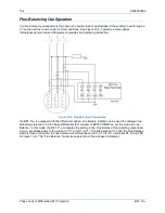
Page 235: ...9424200996 45 5 BE1 11m Terminals and Connectors Figure 45 7 Example of Reversed CT Polarity...
Page 236: ...45 6 9424200996 Terminals and Connectors BE1 11m...
Page 269: ...9424200996 48 15 BE1 11m BESTlogic Plus Figure 48 4 Logic Page 1 for Default Logic...
Page 288: ...49 10 9424200996 Communication BE1 11m Figure 49 14 Modbus Mapping Screen...
Page 306: ...52 4 9424200996 Device Information BE1 11m...
Page 314: ...53 8 9424200996 Configuration BE1 11m Figure 53 3 Display Units Screen...
Page 318: ...54 4 9424200996 Introduction to Testing BE1 11m...
Page 330: ...56 6 9424200996 Commissioning Testing BE1 11m...
Page 336: ...58 4 9424200996 Phase Undervoltage 27P Test BE1 11m...
Page 340: ...59 4 9424200996 Phase Overvoltage 59P Test BE1 11m...
Page 352: ...60 12 9424200996 Auxiliary Overvoltage 59X Test BE1 11m...
Page 360: ...61 8 9424200996 Frequency 81 Test BE1 11m...
Page 364: ...62 4 9424200996 Instantaneous Undercurrent 37 Test BE1 11m...
Page 376: ...63 12 9424200996 Instantaneous Overcurrent 50 Test BE1 11m...
Page 396: ...65 16 9424200996 Inverse Overcurrent 51 Test BE1 11m...
Page 408: ...67 6 9424200996 Power 32 Test BE1 11m...
Page 412: ...68 4 9424200996 Loss of Excitation Reverse Var Based 40Q Test BE1 11m...
Page 426: ...70 10 9424200996 Thermal Curve 49TC Test BE1 11m...
Page 432: ...72 4 9424200996 Starts per Time Interval 66 Test BE1 11m...
Page 436: ...73 4 9424200996 Restart Inhibit Test BE1 11m...
Page 440: ...74 4 9424200996 Virtual Control Switches 43 Test BE1 11m...
Page 450: ...75 10 9424200996 Logic Timers 62 Test BE1 11m...
Page 464: ...79 8 9424200996 Troubleshooting BE1 11m...
Page 480: ...80 16 9424200996 Specifications BE1 11m...
Page 600: ...84 56 9424200996 Settings Calculation Examples BE1 11m Figure 84 70 Logic Page 4 Part 1...
Page 602: ...84 58 9424200996 Settings Calculation Examples BE1 11m...
Page 608: ...85 6 9424200996 BESTCOMSPlus Settings Loader Tool BE1 11m...
Page 609: ......