


FS3 Frame Synchronizer/Converter v1.1r1 12 www.aja.com
Chapter 2 – Controls, Indicators, and
Connections
Overview
The controls, indicators, and connectors illustrated and described in this chapter
allow you to connect, operate, and monitor the FS3 system and to troubleshoot
problems if you encounter them. Becoming familiar with the front and rear panels
also simplifies system installation, setup, and operation.
Front Panel Description
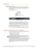
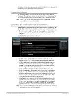
Figure 2. AJA FS3 Front Panel Controls and Indicators
Activity
Indicators:
VID IN
UFC
Proc Amp
FMT ERR
Power and
Status Indicators:
PWR 1
PWR 2
ID
ALARM
Alphanumeric Display:
Line 1=Parameter
Line 2=Parameter value
Line 3=Status/Legend
Line 4=Status/Legend
Select knob:
Scrolls and
selects menus;
Push to undo
changes.
Adjust knob:
Changes
selected value;
Hold down for
default value.
Menu Group Selection Buttons:
Press a button to select
a Menu Group in the display
Status Indicators:
REF, 2SI, LAN, EXT
Alphanumeric Display
The FS3’s control system is designed to be quick and easy to use. The four-line
alphanumeric display shows menus that are numbered and grouped by function.
The menu groups are easily accessed using pushbuttons which correspond one-
to-one with the groups (one button per menu group). The menu lines, which are
23 characters wide, display the following information:
• First line—parameter number and name.
• Second line—the editable value set for a parameter.
• Third and fourth lines—current status, labels, or prompts.
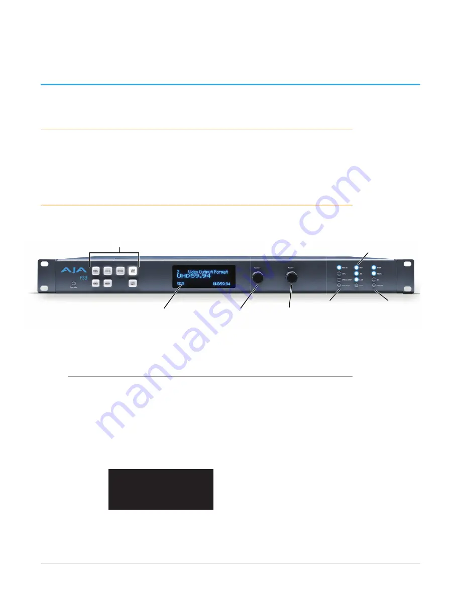
Figure 3. Four Lines of the Front Panel Display
1 Param number & name
2 Current value setting
3 Legend, info or prompt
4 Legend, info or prompt
When you edit a parameter containing multiple values, such as the IP address, the
value currently being edited blinks.