Triggering the Oscilloscope
4
6000 Series Oscilloscope User’s Guide
179
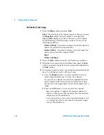
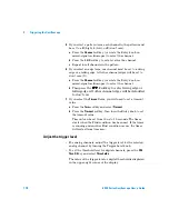
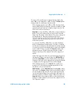
To use SPI triggering
Serial Peripheral Interface (SPI) trigger setup consists of
connecting the oscilloscope to a clock, data, and framing signal.
You can then trigger on a data pattern that occurs at the start of
a frame. The serial data string can be specified to be from 4 to
32 bits long.
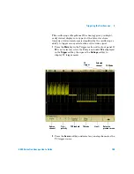
When you press the
Settings
softkey, a graphic will be displayed
showing the current state of the frame signal, clock slope,
number of data bits, and data bit values. Press the
Signals
softkey in the
Settings
menu to see the current source channels
for the clock, data, and frame signals.
•
Press the
More
key in the Trigger section of the front panel,
rotate the Entry knob until
SPI
is displayed in the
Trigger
softkey, then press the
Settings
softkey to display the SPI
trigger menu.
N O T E
For SPI decode information see
Summary of Contents for InfiniiVision DSO6014L
Page 2: ...Agilent Technologies Agilent 6000 Series Oscilloscopes User s Guide...
Page 59: ...58 6000 Series Oscilloscope User s Guide 1 Getting Started...
Page 109: ...108 6000 Series Oscilloscope User s Guide 2 Front Panel Controls...
Page 125: ...124 6000 Series Oscilloscope User s Guide 3 Viewing and Measuring Digital Signals...
Page 251: ...250 6000 Series Oscilloscope User s Guide 5 Making Measurements...
Page 287: ...286 6000 Series Oscilloscope User s Guide 6 Displaying Data Interpreting Decoded LIN Data...
Page 321: ...320 6000 Series Oscilloscope User s Guide 7 Saving and Printing Data...
Page 370: ......


