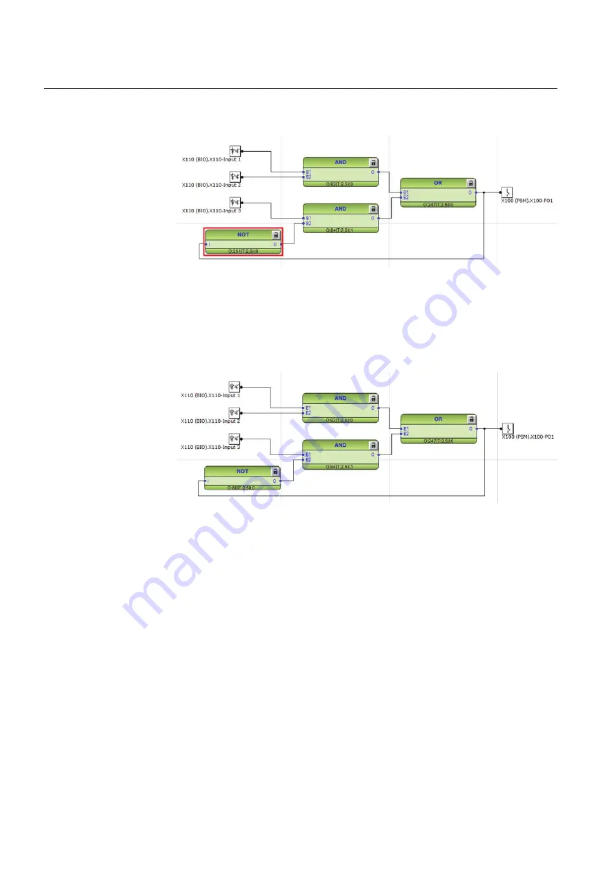
Example shows a simple situation where the execution order causes one cycle time
delay if the NOT port is executed in the order determined by the automatic calculation.
GUID-F8162182-FF21-467A-AEB9-23284CB3FABD V1 EN
Figure 45:
Feedback loop situation with automatically calculated execution
orders
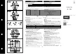
By setting a smaller execution number than in the AND port to where the NOT port
is connected, it is possible to fix the execution order of all functions in a loop so that
they are handled in the same task.
GUID-0C12B88A-0ABE-49DE-9A44-05D213D04922 V1 EN
Figure 46:
Feedback loop situation with manually fixed execution order for NOT
port
Execution number can be changed by right-clicking the function and selecting
Change CycleTime ExecOrder
.
After manually defining the execution number, the function is no longer part of the
automatic execution order calculation. The function can be included back to the
automatic calculation by right-clicking the function and selecting
Include FB in
calculation
.
5.1.5
Configuration parameters
Configuration parameters can be viewed and set with the Parameter Setting tool.
Section 5
1MRS757810 C
Protection and control engineering
70
REC615 and RER615
Engineering Manual


