


InvW2Curr
=No
Then the internal calculations will be:
1
1
2
1
1
2
100
100
%
IDLW1 IDLW2
100
100
%
1 ,
2
,
Diff
V
S
BaseW
BaseW
Bias
V
S
BaseW
BaseW
I
I
I
I
I
I
Max IDLW
IDLW
Max
I
I
I
I
IECEQUATION203 V2 EN-US
(Equation 10)
The phase selection settings for the second instance of the T1PPDIF function shall
be:
PhSelW1
=L2
PhSelW2
=L1
InvW2Curr
=Yes
Then the internal calculations will be:
2
1
2
2
1
2
100
100
%
IDLW1 IDLW2
100
100
%
1 ,
2
,
Diff
U
S
BaseW
BaseW
Bias
U
S
BaseW
BaseW
I
I
I
I
I
I
Max IDLW
IDLW
Max
I
I
I
I
IECEQUATION204 V2 EN-US
(Equation 11)
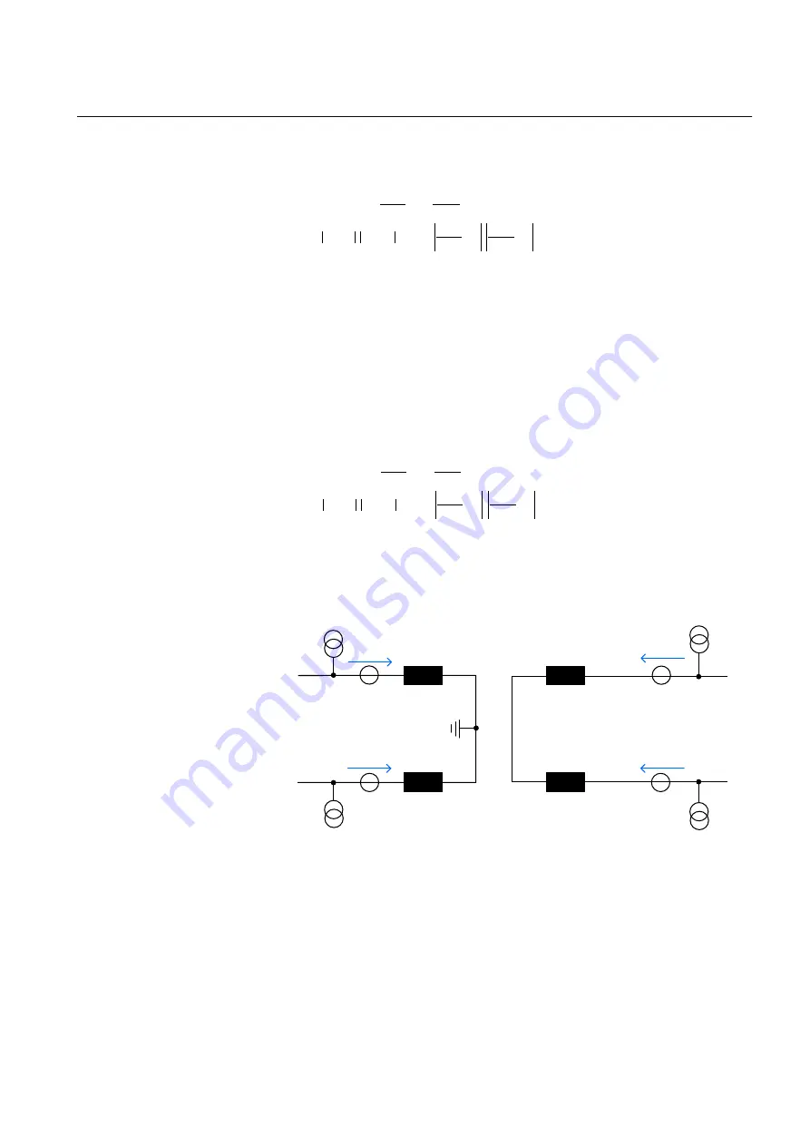
Transformer connection – example 3
GUID-945C3857-BE28-484D-B68F-7C9C3BB05441 v2
IEC15000172-2-en.vsdx
132/66kV
66kV
132kV
I
U
v
I
U
I
S
S
V
I
R
R
IEC15000172 V2 EN-US
Figure 34:
Transformer connection – example 3
The HV currents I
V
and I
U
shall be connected as IL1 and IL2 currents, respectively,
for the winding 1 side towards the T1PPDIF function. The LV currents I
S
and I
R
shall be connected as IL1 and IL2 currents, respectively, for the winding 2 side
towards the T1PPDIF function.
1MRK 506 375-UEN A
Section 6
Differential protection
Railway application RER670 2.2 IEC
87
Application manual
Summary of Contents for RELION RER670
Page 1: ...RELION 670 SERIES Railway application RER670 Version 2 2 IEC Application manual ...
Page 2: ......
Page 22: ...16 ...
Page 48: ...42 ...
Page 70: ...64 ...
Page 80: ...74 ...
Page 100: ...94 ...
Page 210: ...204 ...
Page 364: ...358 ...
Page 384: ...378 ...
Page 468: ...462 ...
Page 494: ...488 ...
Page 504: ...498 ...
Page 505: ...499 ...


