


Substation A
Substation B
Z
lineAB,1
(pos. seq)
Z
lineAB,0
(zero seq)
Z
lineBC,1
(pos. seq)
Z
lineBC,0
(zero seq)
U
0A
U
0B
2I
0
Phase to earth fault
R
N
Z
T,1
(pos. seq)
Z
T,0
(zero seq)
Source impedance
Z
sc
(pos. seq)
IEC16000126-1-en.vsdx
IEC16000126 V1 EN-US
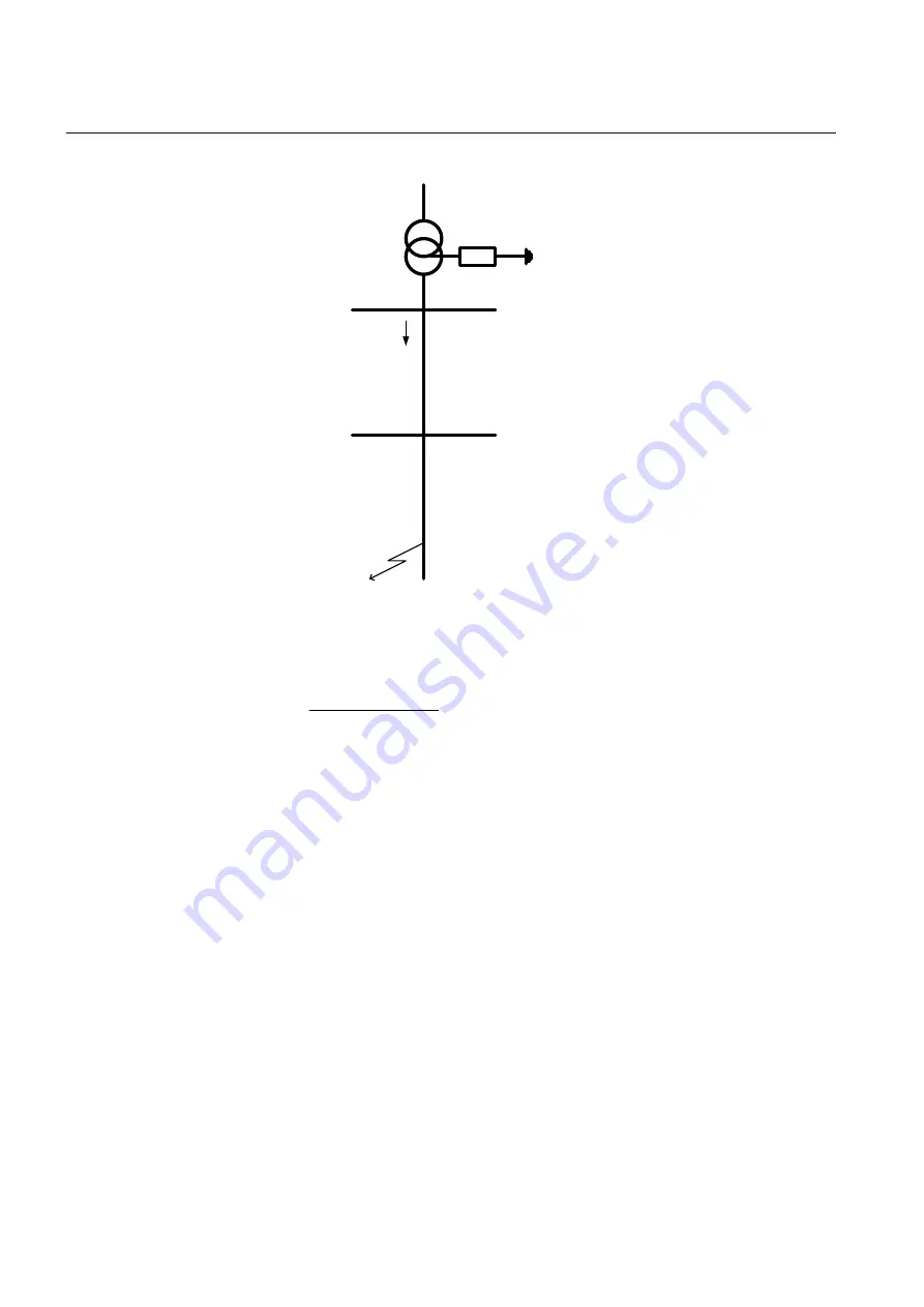
Figure 58:
Equivalent of power system for calculation of setting
The residual fault current can be written:
0
1
0
2
2
2
2
phase
f
U
I
Z
Z
R
IECEQUATION16034 V1 EN-US
(Equation 47)
Where
U
phase
is the phase voltage in the fault point before the fault
Z
1
is the total positive sequence impedance to the fault point. Z
1
= Z
sc
+Z
T,1
+Z
lineAB,1
+Z
lineBC,1
Z
0
is the total zero sequence impedance to the fault point. Z
0
= Z
T,0
+2R
N
+Z
lineAB,0
+Z
lineBC,0
R
f
is the fault resistance.
The residual voltages in stations A and B can be written:
0
0
,0
2
2
A
T
N
U
I
Z
R
IECEQUATION16097 V1 EN-US
(Equation 48)
0
0
,0
,0
2
2
B
T
N
lineAB
U
I
Z
R
Z
IECEQUATION16098 V1 EN-US
(Equation 49)
Section 8
1MRK 506 375-UEN A
Current protection
178
Railway application RER670 2.2 IEC
Application manual
Summary of Contents for RELION RER670
Page 1: ...RELION 670 SERIES Railway application RER670 Version 2 2 IEC Application manual ...
Page 2: ......
Page 22: ...16 ...
Page 48: ...42 ...
Page 70: ...64 ...
Page 80: ...74 ...
Page 100: ...94 ...
Page 210: ...204 ...
Page 364: ...358 ...
Page 384: ...378 ...
Page 468: ...462 ...
Page 494: ...488 ...
Page 504: ...498 ...
Page 505: ...499 ...


