
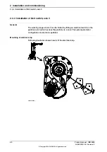

2.4.4 Installation of limit switch, axis 3
General
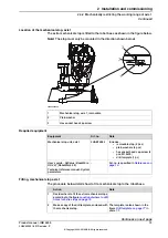
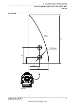
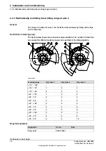
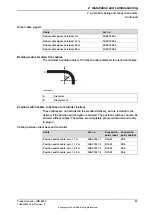
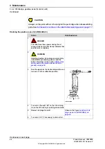
The working range of axis 3 can be limited by fitting an electrical switch on the
gearbox axis 3, which senses the position via a cam. The system parameter
configuration must also be updated.
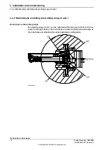
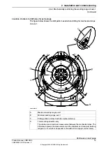
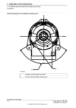
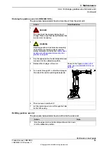
Mounting of eletrical stop
Following illustration shows how to fit the electrical stop.
xx0200000211
80
Product manual - IRB 2400
3HAC022031-001 Revision: P
© Copyright 2004-2018 ABB. All rights reserved.
2 Installation and commissioning
2.4.4 Installation of limit switch, axis 3
Summary of Contents for IRB 2400 Series
Page 1: ...ROBOTICS Product manual IRB 2400 ...
Page 8: ...This page is intentionally left blank ...
Page 18: ...This page is intentionally left blank ...
Page 204: ...This page is intentionally left blank ...
Page 220: ...This page is intentionally left blank ...
Page 232: ...This page is intentionally left blank ...
Page 234: ...This page is intentionally left blank ...
Page 240: ......
Page 241: ......


