
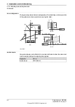
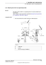
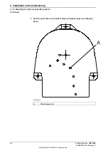

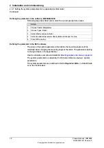
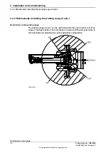
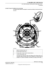
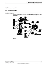
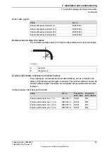
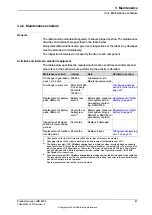
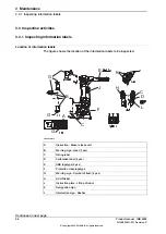
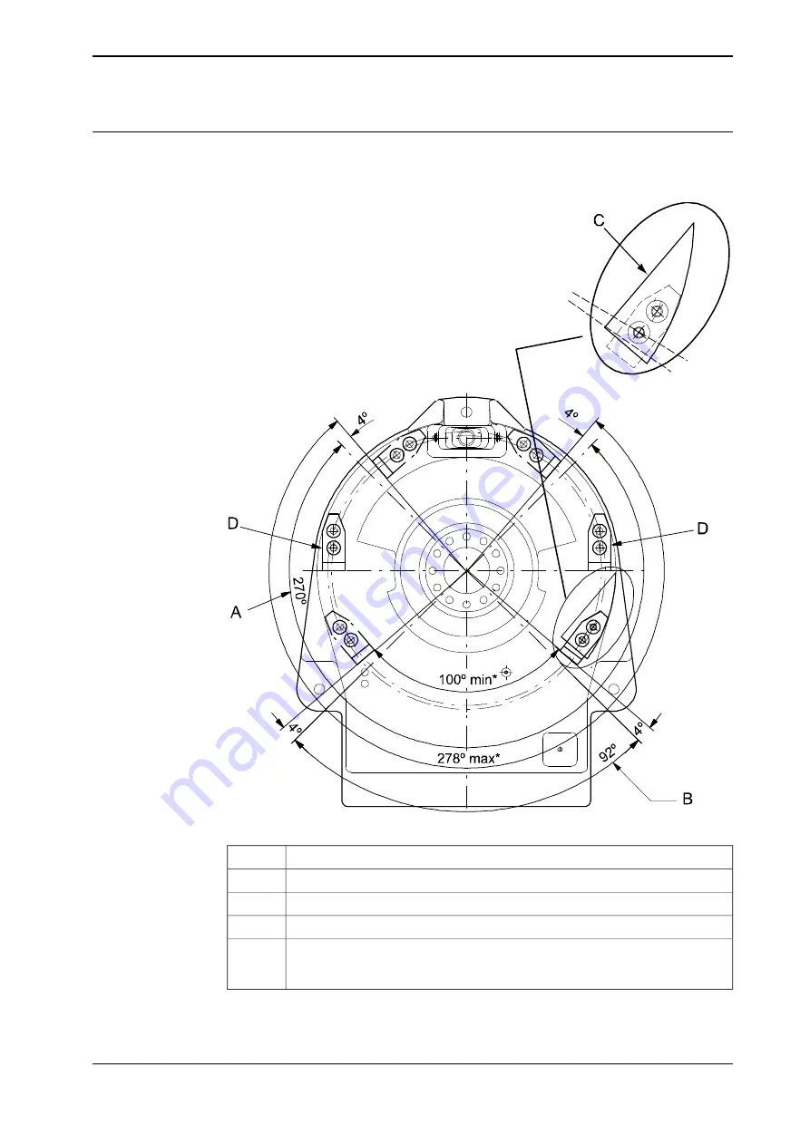
Location of where to drill holes for extra stops
The figure below shows the drill pattern used when drilling for mechanical stops
on axis 1.
xx0200000206
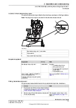
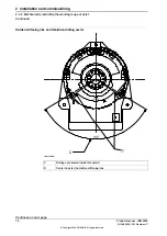
Maximum working range, axis 1
A
Minimum working range, axis 1
B
Drilling pattern enclosed with the mechanical stop.
C
This mounting direction only
D
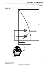
The minimum and maximum measurement between the mechanical stops. The
difference between the measurement and the minimum and maximum working
range is 2 x 4º, which corresponds to the width of the stop pin (at the frame).
*
Continues on next page
Product manual - IRB 2400
75
3HAC022031-001 Revision: P
© Copyright 2004-2018 ABB. All rights reserved.
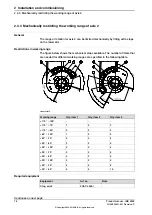
2 Installation and commissioning
2.4.2 Mechanically restricting the working range of axis 1
Continued
Summary of Contents for IRB 2400 Series
Page 1: ...ROBOTICS Product manual IRB 2400 ...
Page 8: ...This page is intentionally left blank ...
Page 18: ...This page is intentionally left blank ...
Page 204: ...This page is intentionally left blank ...
Page 220: ...This page is intentionally left blank ...
Page 232: ...This page is intentionally left blank ...
Page 234: ...This page is intentionally left blank ...
Page 240: ......
Page 241: ......


