


ABB i-bus
®
KNX
Commissioning
© 2008 ABB STOTZ-KONTAKT GmbH
199
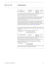
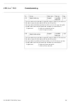
No.
Function
Object name
Data type
Flags
139
Forced operation
Output A
2 bit (EIS 8)
DPT 2.001
C, W
This communication object is enabled if in parameter window
A: Output (20 A/16 AX C-Load)
the parameter
Enable function forced operation
has been selected with the option
yes
and the
parameter
Type of object “Forced operation”
has been selected with 2 bits.
The output can be forcibly operated via this communication object (e.g. by a higher-level
control). The object value directly defines the forced position of the contact:
0 or 1 = The output is not forcibly operated.
2 = The output is forcibly switched off
3 = The output is forcibly switched on
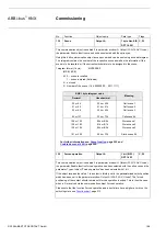
140
Status switch
Output A
EIS 1, 1 bit
DPT 1.001
C, R, T
This communication object is enabled if in parameter window
A: Output (20 A/16 AX C-Load)
the parameter
Enable communication object “Status switch” 1 bit
has been selected with the
option
yes.
You can parameterise whether the communication object value
no, update only
,
after a
change
or
after request
is sent on the bus.
The communication object value directly indicates the current contact position of the switching
relay.
The status value can be inverted.
Telegram value
1 = relay ON or OFF depending on the parameterisation
0 = Relay OFF or ON depending on the parameterisation
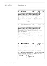
141
Logical connection 1
Output A
1 bit (EIS 1)
DPT 1.002
C, W
This communication object is enables if in the parameter window
-Logic
the parameters
Logical connection 1 active
has been selected with
yes
. The parameter window
- Logic
is
enabled in the parameter window
A: Output (20 A/16 AX C-Load).
Using this communication object the output of the first of two logic objects can be assigned.
The logical connection is defined in the parameter window -
Logic
.
Initially the switch object is then logically linked with the communication object
Logical
connection 1
. The result of this is then logically linked with the communication object
Logical
connection 2
.
For further information see:
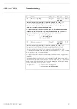
142
Logical connection 2
Output A
1 bit (EIS 1)
DPT 1.002
C, W
See communication object 141.


