Specifications
D184B097U02
FV4000 / FS4000
111
12.9 Temperature of medium
Important
Please note the information in the section titled "Explosion
protection".
Compliance with the permissible temperature range for the
gaskets is mandatory.
FV4000-VT4/VR4
FS4000-ST4/SR4
Standard
-55 ... 280 °C (-67 ... 536 °F)
HT design
-55 ... 400 °C
(-67 ... 752 °F)
-
12.10 Flowmeter insulation
The pipeline may be insulated up to a maximum of 100 mm (4 inch)
upper edge.
Use of trace heating
Trace heating may be used under the following conditions:
•
If it is fixed directly on or around the pipeline
•
If, in the case of existing pipeline insulation, it is installed inside
the insulation (the maximum height of 100 mm (4 inch) must not
be exceeded)
•
If the maximum temperature the trace heating is able to produce
≤
the maximum temperature of the medium
The requirements to be met by integrators set out in EN 60079-
14 must be complied with!
Please note that the use of trace heaters will not impair EMC
protection or generate additional vibrations.
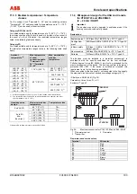
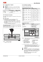
Fig. 59:
Flowmeter insulation
1
Maximum 100 mm (4 inch)
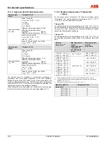
12.11 Ambient conditions
Resistance to climate to DIN 40040
Permissible ambient temperature range
Explosion protection / Model
Temperature range
-20 ... 70 °C (-4 … 158 °F)
None /
VT40 and VR40 / ST40 and
SR40
-55 … 70 °C (-67 … 158 °F)
-20 ... 70 °C (-4 … 158 °F)
1)
Ex ib /
VT41 and VR41 / ST41 and
SR41
-40 … 70 °C (-67 … 158 °F)
1)
-20 ... 60 °C (-4 … 140 °F)
Ex ia /
VT4A and VR4A / ST4A and
SR4A
-30 ... 60 °C (-40 … 140 °F)
-20 ... 60 °C (-4 … 140 °F)
Ex d /
VT42 and VR42 / ST42 and
SR42
-40 ... 60 °C (-40 … 140 °F)
-20 … 70 °C (-4 … 158 °F)
C
FM
US
/
VT43 and VR43 / ST43 and
SR43
-45 … 70 °C (-49 … 158 °F)
1) Category 2D (dust-ignition proof) maximum 60° C (140° F)
Permissible air humidity
Design
Humidity
Standard
Relative humidity max. 85 %,
annual mean
≤
65 %
Climate-proof Relative
humidity
≤
100 % permanent
1)
1
3
4
5
2
70
60
50
40
30
20
0
10
-10
-20 opt. -55
-50
0
50
100
150 160
250
280
400
200
4
4
Fig. 60: Relationship between the temperature of the fluid and the
ambient temperature
1 Ambient
temperature
2 Media
temperature
3 Permissible
temperature
range for standard design
(
≤
280 °C (
≤
536 °F))
4
Installation for medium
temperature > 150 °C
(302 °F)
5
HT design
(
≤
400 °C (
≤
752 °F)),
FV4000-VT4 only
1
) For the supply circuit (terminals 31 / 32) and the switching outputs 41 and 42,
cables suitable for temperatures up to T = 110 °C (230 °F) may be used without
restriction. Cables which are only suitable for temperatures up to
T = 80 °C (176 °F) restrict the temperature ranges. These restrictions also
apply to the VR version (remote design) and the PROFIBUS PA design with
plug
connector.
Important
The legibility of the display can be impaired at temperatures
< 0 °C (< 32 °F) and > 55 °C (> 131 °F). The functionality of
the meter and the outputs remains unaffected by this. Please
refer to the order information for ambient temperatures < -
20 °C (< -4 °F).
Please note the information in the section titled 13
„Transmitter specifications”.
Change from one to two columns
Summary of Contents for FS4000
Page 1: ...Operating Instruction D184B097U02 Vortex Flowmeter Swirl Flowmeter FV4000 FS4000 ...
Page 116: ...Appendix 116 FV4000 FS4000 D184B097U02 ...
Page 117: ...Appendix D184B097U02 FV4000 FS4000 117 ...
Page 118: ...Appendix 118 FV4000 FS4000 D184B097U02 ...
Page 119: ...Appendix D184B097U02 FV4000 FS4000 119 ...
Page 120: ...Appendix 120 FV4000 FS4000 D184B097U02 ...
Page 125: ......


