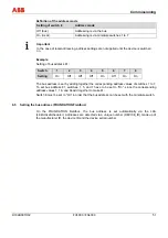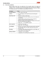
Electrical connections
38
FV4000 / FS4000
D184B097U02
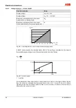
5.2.2.1 Voltage supply, 4 ... 20 mA / HART
Electrical variable
Value
Supply voltage
U
B
≥
14 V DC
Supply voltage
U
S
= 14 ... 46 V DC
Maximum permissible load for the power
supply unit (e. g. display, load)
R
B
Maximum permissible load for the output
circuit (determined by the power supply unit)
R
G00644
S
B
10
15
20
25
30
35
40
45
50
1,6
1,4
1,2
1,0
0,8
0,6
0,4
0,2
0,0
U [V, DC]
[k ]
Ω
R
Fig. 28: Load diagram for current output, load via supply power
In HART communication, the smallest load is 250
Ω
. The load R
E
is calculated on the basis of
the available supply voltage U
S
and the selected signal current as follows:
B
S
E
I
U
R
=
20 mA
4 mA
0
Qmax
Q
1
Fig. 29: Current output
1
Low flow
The measurement value output at the current output is as shown in the figure: Above the low
flow, the current is a straight line that would have 4 mA in Q = 0 and 20 mA in Q = Qmax
operating mode. Due to low flow cutoff, the flow is set to 0 below x % Qmax or the low flow (in
other words, the current is 4 mA).
Summary of Contents for FS4000
Page 1: ...Operating Instruction D184B097U02 Vortex Flowmeter Swirl Flowmeter FV4000 FS4000 ...
Page 116: ...Appendix 116 FV4000 FS4000 D184B097U02 ...
Page 117: ...Appendix D184B097U02 FV4000 FS4000 117 ...
Page 118: ...Appendix 118 FV4000 FS4000 D184B097U02 ...
Page 119: ...Appendix D184B097U02 FV4000 FS4000 119 ...
Page 120: ...Appendix 120 FV4000 FS4000 D184B097U02 ...
Page 125: ......

