Specifications
108
FV4000 / FS4000
D184B097U02
12 Specifications
Change from one to two columns
A
12.1 Nominal diameter selection
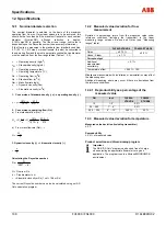
The nominal diameter is selected on the basis of the maximum
operating flow Qv max. If maximum spans are to be achieved, this
should not be less than half the maximum flowrate for each nominal
diameter (Qv
max
DN), although reduction to approx.
0.15 Qv max DN is possible. The linear lower range limit value is
dependent upon the Reynolds number (see accuracy information).
If the flow to be measured is the standard flow (standard condition:
0 °C (32 °F), 1,013 mbar) or mass flowrate, this must be converted to
the operating flow and the most appropriate nominal device diameter
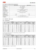
must be selected from the flow range tables (Tables 1, 2, 3).
ρ
= Operating density (kg/m3)
ρ
N = Standard density (kg/m
3)
P
= Operating pressure (bar)
T =
Operating
temperature
(°C)
Qv = Operating flow (m3/h)
Qn = Standard flow (m3/h)
Qm = Mass flowrate (kg/h)
η
= Dynamic viscosity (Pas)
ν
= Kinematic viscosity (m2/s)
1.
Conversion of standard density (
ρ
n) --> operating density (
ρ
)
T
,
,
n
+
×
ρ
+
×
ρ
=
ρ
273
273
013
1
013
1
2.
Conversion to operating flow (Qv)
a) From standard flow (Qn) -->
273
273
013
1
013
1
T
p
,
,
Q
Q
Q
n
n
n
V
+
×
+
=
ρ
ρ
=
b) From mass flowrate (Qm) -->
ρ
=
m
V
Q
Q
3. Dynamic viscosity (
η
) --> kinematic viscosity (
ν
)
ρ
η
=
ν
Calculating the Reynolds number:
(
)
d
2827
Q
Re
⋅
ν
⋅
=
Q = Flow in m3/h
d = Pipe diameter in m
ν
= Kinematic viscosity m2/s (1 cst = 10-6 m2/s)
The current Reynolds number can also be calculated using our AP-
Calc calculation program.
12.2 Measured value deviation for flow
measurement
Deviation in percentage terms from the measured value under
reference conditions (including the transmitter) in the linear
measuring range between Re min and Qmax (see "Measuring
ranges" table).
FV4000-VT4/VR4
FS4000-ST4/SR4
Fluids
≤
± 0,75 %
Gases / Steam
≤
± 1 %
± 0,5 %
Current output
Additional
measurement
uncertainty
< 0,1 %
Temperature effect
< 0,05 % / 10 K
Misalignment associated with installation or deinstallation may affect
the measuring error.
Additional measuring errors may occur if there are deviations from
the reference conditions.
12.2.1 Reproducibility as a percentage of the
measured value
DN
Inch
FV4000-
VT4/VR4
FS4000-
ST4/SR4
15 1/2“
0,3
%
25 ... 250
1“ ... 6“
0,2 %
200 ... 300
8“ ... 12“
0,25 %
0,2 %
12.3 Measured value deviation for temperature
Measured value deviation (including transmitter)
± 2 °C
Reproducibility
≤
0.2 % of measured value
Product selection and dimensioning program
Important
The ABB "AP-Calc" program can be used free of charge
when selecting an appropriate flowmeter for a given
application. The program runs in a Microsoft WINDOWS ®
environment.
Summary of Contents for FS4000
Page 1: ...Operating Instruction D184B097U02 Vortex Flowmeter Swirl Flowmeter FV4000 FS4000 ...
Page 116: ...Appendix 116 FV4000 FS4000 D184B097U02 ...
Page 117: ...Appendix D184B097U02 FV4000 FS4000 117 ...
Page 118: ...Appendix 118 FV4000 FS4000 D184B097U02 ...
Page 119: ...Appendix D184B097U02 FV4000 FS4000 119 ...
Page 120: ...Appendix 120 FV4000 FS4000 D184B097U02 ...
Page 125: ......


