E-IISP Hierarchical Routing Algorithm
63
The crankback mechanism eliminates the need for the original
transmitting station to release and re-establish the call.
The crankback mechanism works as follows: If a virtual channel fails to be
established along one of the links, a RELEASE message will be sent back
to the switch that sent the SETUP message.
automatic retry
After receiving the RELEASE message, the source CoreBuilder 7000 family
ATM switch again attempts to establish a virtual channel but this time via
an alternate path. The switch determines the alternate path automatically
with the routing table that was established during the first connection
attempt. The routing table holds all the connection alternatives. The
CoreBuilder 7000 family ATM switch remembers which connection was
used in the failed attempt and chooses a different connection the second
time, resulting in a new and different path to the destination.
The availability of alternate paths for connections depends on the
addressing scheme that was used in setting up the network. Alternate
connections need to have the same match type (see “Alternate Routes”
on page 63).
Alternate Routes
When you plan your network according to the hierarchical addressing
scheme, you must carefully provide alternate, redundant routes between
nodes. Failure to do so will result in infinite loops. To assist you, follow the
rules presented in “Rules for Creating Alternate Routes” described in this
section.
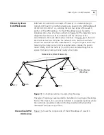
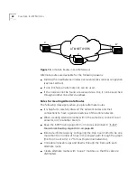
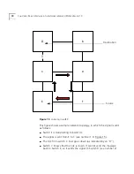
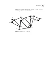
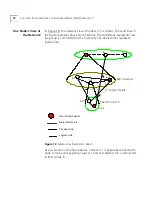
For example, in the network of Figure 14, there are three ways (paths) to
reach node B1 from node A through the ATM network: Link-1 and link-2
are connected directly to node B1, and link-3 is connected through node
B.
Summary of Contents for CoreBuilder 7000
Page 12: ......
Page 30: ...30 CHAPTER 1 ATM NETWORK BASICS...
Page 32: ...32 CHAPTER 1 ATM NETWORK BASICS...
Page 34: ...34 CHAPTER 1 ATM NETWORK BASICS Figure 8 LANE Network over WAN...
Page 96: ...96 CHAPTER 4 PRIVATE NETWORK TO NETWORK INTERFACE PNNI VERSION 1 0...
Page 184: ...184 CHAPTER 7 LAN EMULATION VERSIONS 1 0 AND 2 0...
Page 206: ...206 CHAPTER 9 DEVICE MANAGEMENT...
Page 222: ...222 APPENDIX A TECHNICAL SUPPORT...
Page 234: ...234 APPENDIX B PROTOCOLS AND INTERFACES...
Page 238: ...238 APPENDIX C COREBUILDER 7000 FAMILY ATM SWITCH SPECIFICATIONS...
Page 242: ...242 APPENDIX D SAFETY INFORMATION...

