background image

3Com Corporation L

IMITED

 W

ARRANTY

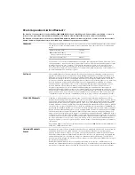
The duration of the warranty for the CoreBuilder 7000/7000HD Chassis and Switch Engine is: Enhanced One-year Limited -— return to 
factory for free repair. One year warranty with 90 days of Advance Hardware Replacement service, subject to availability.

The duration of the warranty for all other CoreBuilder 7000 Hardware Modules is: One Year limited — return to factory for free repair. 
Advance Hardware Replacement service is available for an additional fee, subject to availability. 

H

ARDWARE

3Com warrants its hardware products to be free from defects in workmanship and materials, under normal 
use and service, for the following lengths of time from the date of purchase from 3Com or its authorized 
reseller:

If a product does not operate as warranted above during the applicable warranty period, 3Com shall, at its 
option and expense, repair the defective product or part, deliver to Customer an equivalent product or part 
to replace the defective item, or refund to Customer the purchase price paid for the defective product. 
All products that are replaced will become the property of 3Com. Replacement products may be new or 
reconditioned. Any replaced or repaired product or part has a ninety (90) day warranty or the remainder of 
the initial warranty period, whichever is longer.

S

OFTWARE

3Com warrants that the software programs licensed from it will perform in substantial conformance to the 
program specifications therefor for a period of ninety (90) days from the date of purchase from 3Com or its 
authorized reseller. 3Com warrants the media containing software against failure during the warranty period. 
No updates are provided. 3Com’s sole obligation with respect to this express warranty shall be (at 3Com’s 
discretion) to refund the purchase price paid by Customer for any defective software products, or to replace any 
defective media with software which substantially conforms to applicable 3Com published specifications. 
Customer assumes responsibility for the selection of the appropriate applications program and associated 
reference materials. 3Com makes no warranty or representation that its software products will meet 
Customer’s requirements or work in combination with any hardware or applications software products 
provided by third parties, that the operation of the software products will be uninterrupted or error free, or that 
all defects in the software products will be corrected. For any third party products listed in the 3Com software 
product documentation or specifications as being compatible, 3Com will make reasonable efforts to provide 
compatibility, except where the non-compatibility is caused by a “bug” or defect in the third party's product.

Y

EAR

 2000 W

ARRANTY

In addition to the Hardware Products Warranty and Software Products Warranty identified above, 3Com 
warrants that all Heritage 3Com products sold or licensed to Customer on and after January 1, 1998 that are 
date sensitive will continue performing properly with regard to such date data on and after January 1, 2000, 
provided that all other products used by Customer in connection or combination with the 3Com products, 
including hardware, software, and firmware, accurately exchange date data with the 3Com products, with the 
exception of those products identified at 3Com’s Web site, http://www.3com.com/products/yr2000.html, as 
not meeting this standard. A product is considered a “Heritage 3Com product” if it is a member of a product 
family which was manufactured by 3Com prior to its merger with US Robotics Corporation. This Year 2000 
limited warranty does not apply to Heritage US Robotics Corporation products. If it appears that any such 
product does not perform properly with regard to such date data on and after January 1, 2000, and Customer 
notifies 3Com before the later of April 1, 2000, or ninety (90) days after purchase of the product from 3Com 
or its authorized reseller, 3Com shall, at its option and expense, provide a software update which would effect 
the proper performance of such product, repair such product, deliver to Customer an equivalent product to 
replace such product, or if none of the foregoing is feasible, refund to Customer the purchase price paid for 
such product. 

Any software update or replaced or repaired product will carry a Year 2000 Warranty for ninety (90) days or 
until April 1, 2000, whichever is later. 

O

BTAINING

 W

ARRANTY


S

ERVICE

Customer must contact 3Com’s Corporate Service Center or an Authorized 3Com Service Center within the 
applicable warranty period to obtain warranty service authorization. Dated proof of purchase may be 
required. Products returned to 3Com’s Corporate Service Center must be pre-authorized by 3Com with a 
Return Material Authorization (RMA) number marked on the outside of the package, and sent prepaid and 
packaged appropriately for safe shipment, and it is recommended that they be insured. The repaired or 
replaced item will be shipped to Customer, at 3Com’s expense, not later than thirty (30) days after receipt of 
the defective product by 3Com.

Dead- or Defective-on-Arrival. 

In the event a product completely fails to function or exhibits a defect in 

materials or workmanship within the first forty-eight (48) hours of installation but no later than thirty (30) days 
after the date of purchase, and this is verified by 3Com, it will be considered dead- or defective-on-arrival 

Network Interface Cards

Lifetime

Other hardware products

*unless otherwise specified above

1 year*

Spare parts and spares kits

90 days

Summary of Contents for CoreBuilder 7000

Page 1: ...http www 3com com CoreBuilder 7000 Family ATM Switches Operations Guide Software Version 4 55 Base and Extended Part No DOA3700 0AAA02 Published January 2000...

Page 2: ...and the software described herein are provided to you subject to the following All technical data and computer software are commercial in nature and developed solely at private expense Software is del...

Page 3: ...ETWORK BASICS ATM Overview 19 ATM Cell Structure 20 Advantages of Using Fixed Length Cells 20 ATM Layers 21 Physical Layer 22 ATM Layer 22 ATM Adaptation Layer AAL 22 Functional Planes 22 User Plane 2...

Page 4: ...of Attachment 51 3 E IISP PROTOCOL Introducing Enhanced Interim InterSwitch Protocol E IISP 53 IISP vs E IISP 53 Features of E IISP 54 Hierarchy in an E IISP Network 55 Hierarchical ATM Addressing 55...

Page 5: ...Signaling Protocol 87 PNNI Signaling 87 Establishing a Channel in PNNI with a Flat Network 88 Alternate Routing and Crankback 89 Establishing a Channel in a Hierarchical Network 91 Alternate Routing...

Page 6: ...C Algorithm 117 UNI Signaling 4 0 Features 120 ATM Anycast Capability 120 Signaling of Individual QoS Parameters 121 Message Conversion Between Signaling Protocols 122 Quality of Service Parameters 12...

Page 7: ...139 LAN Emulation Server LES 140 Broadcast and Unknown Server BUS 140 LAN Emulation Configuration Server LECS 140 Configuring LANE Into Your Network 141 Emulated LAN Connections 141 Control VCCs 141...

Page 8: ...Factory Default Configuration 164 LMA Security Commands 165 LANE Version 2 0 166 Improved Features 166 Multi Protocol over ATM MPOA 167 Quality of Service QoS 167 New Well known LECS Address 167 Loca...

Page 9: ...lt VLANs 188 VLANs in a CoreBuilder 7600 Card 189 Virtual LANs for Three Workgroups 192 9 DEVICE MANAGEMENT Overview 193 Local Management Application LMA 193 Communication Methods 194 Security 194 SNM...

Page 10: ...212 Identifying the Active Switching Module 212 Conditions for Switch over to Redundant Module 212 Switch over Phases 213 Switching Module Configuration Database 213 Information Based on the MAC Addre...

Page 11: ...OAM 229 ATM Layer OAM 229 ATM Adaptation Layer AAL 231 AAL1 231 AAL2 231 AAL3 4 231 AAL5 231 C COREBUILDER 7000 FAMILY ATM SWITCH SPECIFICATIONS D SAFETY INFORMATION Guidelines for Avoiding Bodily Ha...

Page 12: ......

Page 13: ...is intended for the system or network administrator who uses the CoreBuilder 7000 family ATM switch It assumes a working knowledge of local area network LAN operation and a familiarity with communica...

Page 14: ...about ATM switching Chapter 6 Information about LAN emulation Chapter 7 Information about virtual networks Chapter 8 Information about how to manage the CoreBuilder 7000 Chapter 9 Information about sw...

Page 15: ...or port Commands The word command means that you must enter the command exactly as shown and then press Return or Enter Commands appear in bold Example To remove the IP address enter the following com...

Page 16: ...ly ATM switch Release Notes on separate CD ROM The release notes contain information about the latest software release The complete documentation for the CoreBuilder 7000 family ATM switches is shown...

Page 17: ...SuperStack II Switch 2700 Adminstration Guide DUA2700 OCAA02 ATMvLAN Manager User Guide UNIX 4 22 09 1046 002 ATMvLAN Manager User Guide 97 Windows NT 09 1112 001 Table 4 Related Documentation Docume...

Page 18: ...he 3Com Year 2000 Web page http www 3com com products yr2000 html Learn about ATM and how it is implemented in the CoreBuilder 7000 family ATM switch Management Guide Learn about LAN Emulation and how...

Page 19: ...d by CCITT and ANSI standards for carriage of a complete range of user traffic on any User to Network Interface UNI and to facilitate multimedia networking between high speed devices at multi megabit...

Page 20: ...roper destination The cell header also provides the network with the ability to implement congestion control and traffic management mechanisms Figure 1 presents the structure of the ATM cell Figure 1...

Page 21: ...ferred at the same time With ATM the same connection can be used for phone fax video data and other information simultaneously This multiprotocol advantage also offers scalability greatly reducing the...

Page 22: ...assembly SAR on cells It formats data into the 48 byte ATM cell payload in effect adapting applications to the cell based ATM layer Once the ATM cells reach their destination they are reconstructed in...

Page 23: ...s about LAN Emulation Control Plane Establishes the connections required for a call passing between the two devices This includes the signaling procedures for establishing a switched virtual channel S...

Page 24: ...0 with one or two ATM interfaces ATM Network Examples In this section several examples of ATM networks and details of how they are built are presented Classical IP ATM Networks The simplest ATM Networ...

Page 25: ...nsmission are connected through ATM adapters to the CoreBuilder 7000 family ATM switch Figure 4 The CoreBuilder 7000 Family ATM Switch in a Simple Workgroup Figure 4 shows the CoreBuilder 7000 family...

Page 26: ...M protocol to Ethernet Token Ring FDDI and so forth In addition the router can be used for WAN connectivity Figure 5 shows a network incorporating multiple CoreBuilder 7000 family ATM switches and a N...

Page 27: ...data transmission across the ATM network An ATM edge device can be a separate unit like the SuperStack II Switch 2700 or it can be a CoreBuilder 7x00 series interface card installed in a CoreBuilder...

Page 28: ...e LAN Emulation clients NETBuilder II A CoreBuilder 2500 supports FDDI rings Enterprise Network This section describes the power modularity and flexibility of the CoreBuilder 7000 family ATM switches...

Page 29: ...h a CoreBuilder 2500 switch First Second and Third Floor Network Edge The CoreBuilder 7000 ATM switches on the first and second floors serve as edge devices the CoreBuilder 7200 and 7400 interface mod...

Page 30: ...30 CHAPTER 1 ATM NETWORK BASICS...

Page 31: ...y backbone to the SuperStack II 2700 switch edge devices and a primary backbone down to the network core The third floor has a legacy Token Ring network connected to the ATM backbone through the Super...

Page 32: ...32 CHAPTER 1 ATM NETWORK BASICS...

Page 33: ...the connections where the CoreBuilder 7000 ATM switch in the enterprise headquarters has the LES and LECS LANE services and provides the multicast capability across the WAN The PABX units in each netw...

Page 34: ...34 CHAPTER 1 ATM NETWORK BASICS Figure 8 LANE Network over WAN...

Page 35: ...er device and an ATM switch Network Network Interface NNI the interface between an ATM switch and an edge device or between two switches See Chapter 3 for more details on NNI Interim InterSwitch Proto...

Page 36: ...5 6 8 7 RX T X MM RX T X 100 FX RX T X MM RX T X 100 FX RX T X MM RX T X 100 FX RX T X MM RX T X 100 FX RX T X MM RX T X 100 FX RX T X MM RX T X 100 FX RX T X MM RX T X 100 FX RX T X MM RX T X 100 FX...

Page 37: ...ase database MIB Each object defined in the MIB has a name a syntax and an encoding The UNI ILMI objects are organized in a standard MIB structure there is one UNI ILMI MIB structure instance for each...

Page 38: ...ion provides the following services Initialization time exchange of addressing information Restrictions on network prefix user part combinations Acceptance of unassigned network prefixes Rejection of...

Page 39: ...of information related to the group address within the network This variable supports the group address of an ATM device and the Anycast facility Anycast is the ability to allow an application to requ...

Page 40: ...stered at an ATM port depends on the type of CoreBuilder 7000 switch and the software version as shown in Table 5 Referencing Calls by Destination ATM Address Member ID For easy reference each ATM add...

Page 41: ...After the polling facility determines that the ILMI connection has failed a period of about 10 minutes the ILMI restarts its operation on that port after clearing all previous information including r...

Page 42: ...NI protocol stack Auto Configuration and Auto Discovery The general concept of automatic configuration in the CoreBuilder 7000 switch is comprised of two specific processes auto discovery and auto con...

Page 43: ...or communicating with a 3Com network device node IISP for communicating with a third party network device node NNI PNNI for communicated between network devices node PNNI is available in version 4 5 e...

Page 44: ...the IME type according to the tables below The following tables show how auto discovery operates for each of the three types of peer switch In all the tables the local switch is a 3Com switch running...

Page 45: ...he LMA to reset the interface type see Update Port Interface Type on page 123 in the Management Guide Table 10 shows how this is done Table 8 Auto Discovery of Interface Type for 3Com Switch ILMI 4 0...

Page 46: ...setting the interface see Update Port Interface Type on page 123 in the Management Guide Table 13 shows how this is done E IISP IISP E IISP Set to E IISP manually IISP E IISP Set to E IISP manually E...

Page 47: ...termined according to the flash values Manual Discovery As mentioned previously when auto discovery does not operate you use LMA to determine the interface type and the IME type This is called manual...

Page 48: ...n The adjacent IMEs inform each other of their capabilities and jointly determine the maximum parameter values they have in common see Table 6 for auto configuration parameter list ILMI Version UNI Si...

Page 49: ...CI range is determined For examples see Display Auto Configuration Results on page 140 in the Management Guide Influencing Auto Configuration via LMA UNI Version You can use LMA to influence the resul...

Page 50: ...ach and every parameter via LMA Modification of Local Attribute When you change any of the following parameters in the Virtual Path Group or in the Virtual Channel Group by manual configuration an app...

Page 51: ...ollowing variables are polled atmfPortMyIfIdentifier sysUpTime atmfMySystemIdentifier Network Management IP address The IME compares the current values of these objects returned in an ILMI response me...

Page 52: ...er ILMI 3 1 port the Change of Attachment Point mechanism is disabled and you need to restart the IME manually using LMA to re activate the Change of Attachment Point mechanism Change of Attachment an...

Page 53: ...them In addition the CoreBuilder 7000 family ATM switch employs a proprietary hierarchical routing algorithm see Routing Internal Links on page 125 This hierarchical routing algorithm requires that t...

Page 54: ...tial prefix with an asterisk to mark the end of the significant bytes and allows tree hierarchical definition from the tree top without listing all the prefixes of this tree IISP does not provide for...

Page 55: ...e network core Each subordinate switch can also have switches attached to it As you progress down the hierarchy the node name or ID is lengthened to include the parent node Finally all of the roots A...

Page 56: ...AREA are not fixed by the system and are available for definition by the operator as shown in Figure 12 AFI Specific Fields AFI RD AREA ESI SEL Network Prefix User Table 17 Fields of the ATM Address F...

Page 57: ...the remaining 7 digits are zero putting as the second digit has the same effect it marks the end of the significant digits The second digit identifies all switches that are attached to the root switch...

Page 58: ...its neighboring CoreBuilder 7000 family ATM switches receives the message and stores the received network prefix together with the port number on which the message was received In this way each CoreB...

Page 59: ...00 A5 3 Assign the third level switches 47 00 00 00 00 00 00 00 00 A2 7 and 47 00 00 00 00 00 00 00 00 A1 53 4 Define the fourth level switches in a similar manner This defines a tree whose common el...

Page 60: ...dressing on page 55 and on the fact that each switch knows the net prefix of the ATM address of each of its NNI neighbors as well as the full ATM address of each UNI neighbor In principle the algorith...

Page 61: ...the destination address For example A has neighbors B B1 and B2 The destination address is B11 According to the definition both B and B1 are best matches because they fit entirely into the destination...

Page 62: ...ber of hops exceeds a preset limit a looping condition is declared and a RELEASE message is returned to the sender terminating the process unsuccessfully with no route established Selecting the Hop Li...

Page 63: ...lder 7000 family ATM switch remembers which connection was used in the failed attempt and chooses a different connection the second time resulting in a new and different path to the destination The av...

Page 64: ...fully draw all the network nodes and their connections to have a general overview of the entire network When creating alternate routes within the same tree connect to an ancestor not to another branch...

Page 65: ...nate links provided that these links have the appropriate addressing The routing algorithm distinguishes between different types of address matching among the NNI neighbors exact match best match and...

Page 66: ...failover redundancy is required for LANE redundancy to work for more information about planning for LANE redundancy see LANE Redundancy Planning on page 160 One special case of LANE redundancy is LEC...

Page 67: ...uide PNNI is dynamic as it enables the establishment of a call specifically catered to the needs of the session data voice or video It knows in advance the QoS Quality of Service needed for each type...

Page 68: ...to its destination The signaling protocol used in point to point P2P and point to multipoint P2M connections across the ATM network is based on the ATM Forum UNI 3 1 Signaling Specifications Addition...

Page 69: ...recommended to use PNNI when your network has more than 15 switches there is a need for scalability and interoperability and you feel that QoS based routing is important PNNI is also recommended when...

Page 70: ...e signal is sent as follows Switch E is transmitting to Switch A The signal is sent from E to C see number 1 in Figure 15 The link from switch C to A goes down as indicated by an X Switch C knows that...

Page 71: ...Organizing a Network Hierarchy Information Exchange in PNNI Uplinks in a Hierarchy Organizing a Network Hierarchy PNNI allows you to work in a hierarchical structure Although this chapter will explain...

Page 72: ...dition to the peer group leader there is also a border node These nodes have at least one link that crosses the peer group boundary These nodes may be peer group leaders It is the border node s that h...

Page 73: ...lat network which has 17 nodes is shown Each node is denoted by a letter and 2 numbers X 1 1 Figure 16 A Network With No Hierarchy A 1 1 A 1 2 A 1 3 A 1 4 A 1 5 A 1 6 A 1 7 A 1 8 A 1 9 A 2 0 A 2 1 A 2...

Page 74: ...of the reachable addresses for its group For example it would broadcast the name of the group but not the individual members This common information is also referred to as aggregated information In F...

Page 75: ...Links between two nodes in the same peer group are not aggregated Links inside a peer group are horizontal links whereas links between two peer groups are outside links When a link becomes operationa...

Page 76: ...presents how the group is summarized in the hierarchy The dashed lines represent logical links Figure 18 Network as Node A 3 1 Sees It As you can see in the figure above node A 3 1 is physically conne...

Page 77: ...sage only to the nodes to which they are directly connected They receive hello messages from their neighbors and begin to build a list of local state information This information includes the identity...

Page 78: ...s peer group is put together into a new packet of information called a PTSE PNNI Topology State Element PTSE PTSE is the smallest collection of PNNI routing information that is flooded as a unit over...

Page 79: ...on Topology State Information Topology state parameters characteristics of the links and characteristics of the nodes Reachability Information Addresses and address prefixes which describe the destina...

Page 80: ...ate a peer group leader and parameters via the LME see Get PGL Priority on page 394 in the Management Guide Once the peer group leader has been elected it raises its priority by 50 This is to ensure t...

Page 81: ...plete topology database for each node has been filled Figures 6 and 7 show the next two hierarchical levels thereby completing the process Figure 22 Hierarchy Level 2 A 1 A 2 A 3 A 3 2 A 3 1 A 1 3 A 1...

Page 82: ...y to the other nodes in this hierarchical level In turn they pass all the information they collected from the nodes in the group downstream to their respective children nodes nodes that are lower in A...

Page 83: ...rarchy to a logical group node in a higher level This link represents the connection from the border node to its neighbor Uplinks are shown for the second level hierarchy group A in Figure 24 Figure 2...

Page 84: ...is designed to be hierarchical it will also allow addresses that do not fit into any hierarchy The ATM address has 20 bytes The 20 bytes are divided as follows 13 bytes for hierarchical positioning Pe...

Page 85: ...or as long as that connection remains open Therefore it is critical that PNNI selects the path correctly This selection is also known as source routing PNNI allows the network manager to specify the Q...

Page 86: ...ll connection setup requests This implies that the first node in the path the source selects the entire path to the destination The path is encoded as a Designated Transit List DTL which is explicitly...

Page 87: ...used for call connection establishment and clearing over ATM interfaces It is based on a subset of UNI 4 0 signaling specifications It makes use of the information that was gathered from the topology...

Page 88: ...hs that the signal can take Based on reachability QoS metrics and current information available about the links the path from A 1 1 to A 2 6 is chosen and a DTL is created Since the network has no gro...

Page 89: ...witch detects this change it does not close the connection and send a disconnect message Instead it hops backwards or cranksback In crankback hops are decreased The switch will crankback to a point wh...

Page 90: ...back 6 hops These hops are decreased from the hop counter Node A 1 1 will choose a new path and update its topology database The new topology database information is transmitted as a PTSE message as d...

Page 91: ...hown in Figure 27 will be used Node A 1 1 wants to establish a connection to send data to node A 2 6 v X X v A 1 1 A 1 2 A 1 3 A 1 4 A 1 5 A 1 6 A 1 7 A 1 8 A 1 9 A 2 0 A 2 1 A 2 2 A 2 3 A 2 4 A 2 5 A...

Page 92: ...ansmission is A signal with PVPC Permanent Virtual Path Connection and PVCC Permanent Virtual Channel Connection is created and a set of DTLs are generated The connection is established and the data i...

Page 93: ...rest of the channel in that direction Figure 32 shows the same signal with a bad connection between two switches Figure 32 Signal Failure in a Hierarchical Network The signal between nodes B 2 1 and B...

Page 94: ...abase The new topology database information is transmitted as a PTSE message as described previously and will be propagated throughout the entire network After the topology databases are updated an al...

Page 95: ...sources This chapter presented PNNI in theory Details on how to implement and configure the PNNI network are located in Chapter 13 in the Management Guide v X X v C 1 1 C 1 2 A 3 2 A 3 1 A 1 3 A 1 1 A...

Page 96: ...96 CHAPTER 4 PRIVATE NETWORK TO NETWORK INTERFACE PNNI VERSION 1 0...

Page 97: ...ls VP Tunneling Signaling External Links Signaling AAL Call Admission Control UNI Signaling 4 0 Features Routing Internal Links Physical Link Failure Indicator Virtual Channels A virtual channel is a...

Page 98: ...as 3 associates the input port of the switch with the correct output port ATM Edge Device ATM Edge Device Destination Station Transmitting Station ATM Switch The virtual channel starts at the ATM edge...

Page 99: ...ble like the external link but is rather a correspondence between the adjacent external links which is stored in the internal memory matrix of the switch The ATM switch stores the correspondence 3 bet...

Page 100: ...the external management station to set up virtual channels The characteristics of the SVC connection include Connections initiated by the user application Connections established and released dynamica...

Page 101: ...d one ILMI channel VPI VCI 0 16 you can set up eight VP tunnels in a single port corresponding to the eight possible VP values Table 24 Comparison of SVC and PVC SVC PVC Demand connections Permanent c...

Page 102: ...and a tunnel type P2P or P2M to the tunnel VP Tunneling through a WAN VP Switch A common application of the VP tunneling capability is to allow a CoreBuilder 7000HD switch to establish a NNI connectio...

Page 103: ...cast Channels When setting up an emulated LAN over a WAN VP switch you need to allocate one channel needs for multicast transmissions to handle the multicast messages of the LES BUS server Providing t...

Page 104: ...MIB UNI signaling and management functions The Virtual UNIs are distinguished by their VPI values Signaling External Links This section describes establishing a switched virtual channel by signaling...

Page 105: ...Dynamic VPI VCI assignment Traffic parameters exchange Characteristic per call per application Signaling Messages The signaling protocol that establishes the connection consists of a command set with...

Page 106: ...llowing elements Destination station address Connection identifier VPI VCI proposal Network service ATM traffic descriptors QoS class Transit network AAL parameters CALL PROCEEDING Message The CALL PR...

Page 107: ...n the signaling dialog with its attached ATM device The profile can be either network or user When the CoreBuilder 7000 family ATM switch port is connected to an end station or edge device the CoreBui...

Page 108: ...or VP links that connect two endpoints and enable data flow to and from both endpoints ATM Edge Device ATM Edge Device Destination Station Transmitting Station ATM Switch The ATM switch accepts or re...

Page 109: ...the connection characteristics except for VPI VCI If the switch can provide the requested service and finds the route to the destination it allocates a value of VPI VCI optionally answers with CALL P...

Page 110: ...VCI The SETUP message also contains a point to multipoint flag The connection to the first leaf proceeds as in a point to point connection The connection to the second destination leaf is initiated b...

Page 111: ...These timers determine when an expected response to a message is overdue They are set to the expected response time when the message is sent and decrement towards zero If they reach zero before the r...

Page 112: ...WLEDGE received T316c 450 VCC RESTART sent RESTART ACKNOWLEDGE received for the VCC T317 450 RESTART received Cancel all call references T322 20 STATUS ENQUIRY sent STATUS DISCONNECT RELEASE or RELEAS...

Page 113: ...OCEEDING received CONNECT or DISCONNECT received T313 20 RELEASE received sent RELEASE COMPLETE received T316 600 PORT RESTART sent RESTART ACKNOWLEDGE received T316c 450 VCC RESTART sent RESTART ACKN...

Page 114: ...f 16 messages called PDUs Protocol Data Units together with a set of watchdog timers The SD and SDP PDUs carry the signaling protocol described previously The watchdog timers allow the system to conti...

Page 115: ...wledgment No Response Maximum time between receipt of a STAT PDU in an active connection CC The connection control timer determines the time between transmission of BGN END or RS PDUs as long as an ac...

Page 116: ...e displayed and updated by management Except where designated these parameters are per port UNI Q93B signaling timers for all ports UNI Q93B signaling protocol VPI VCI configuration parameters QSAAL s...

Page 117: ...service categories supports the extended QoS parameters Acceptable Peak to Peak Cell Delay Variation for both directions indicates the calling user s highest acceptable least desired peak to peak CDV...

Page 118: ...ons multiplied by the variance factor VF a a relative measure of the cell rate margin normalized by the variance of the aggregate rate The actual allocated capacity AAC is the sum of ARR and CRM The a...

Page 119: ...e Class A connection with a unspecified bit rate UBR service is never rejected because of bandwidth considerations However the selective cell discard may be used on a UBR connection to limit its influ...

Page 120: ...a server in the group fails the user is directed to establish a connection with another server in group A calling user requests an ATM anycast capability by sending a SETUP message that contains the...

Page 121: ...rresponding cumulative value of the parameter The cumulative forward and backward values of individual QoS parameters indicated by the user in the SETUP message if present include the cumulative value...

Page 122: ...transfer characteristics provided by the network may change after the connection is established A flow control mechanism is specified which supports several types of feedback to control the source ra...

Page 123: ...ting up before the control loop is established Cumulative RM Fixed Round Trip Time FRTT The sum of the fixed and propagation delays from the source to a destination and back Rate Increase Factor RIF C...

Page 124: ...may even be silent for periods of time Cells which are delayed beyond the value specified by the maximum cell transfer delay maxCTD are assumed to be of significantly reduced value to the application...

Page 125: ...ks As discussed previously a virtual channel is made up of two types of links External links connections between ports of adjacent ATM devices Internal links between input and output ports of an ATM d...

Page 126: ...rs If a match is found the SETUP message is sent on to the appropriate UNI port finishing the process successfully with a route established 3 If no match is found among its UNI neighbors the CoreBuild...

Page 127: ...SETUP message is forwarded to the NNI neighbor to establish an external link connection to it Hop Limit Avoiding Loops One step of forwarding the SETUP message between NNI neighbors is called a hop I...

Page 128: ...itch remembers which connection was used in the failed attempt and chooses a different connection the second time resulting in a new and different path to the destination The availability of alternate...

Page 129: ...anism the CoreBuilder 7000 initiates failover immediately after physical link failure The link failure detection hardware has the following properties Detects a link failure much faster than detection...

Page 130: ...R 5 ESTABLISHING ATM CHANNELS Table 34 Parameters in Selecting Link Failure Sensitivity Sensitivity Time seconds Speed of Detection Certainty of Detection High 5 High Low Medium 15 Medium Medium Low 3...

Page 131: ...pt of virtual channel what a virtual channel is and how it is built This chapter discusses how ATM data travels or is switched over a virtual channel This chapter provides basic concepts and informati...

Page 132: ...ernal links are stored in the switch ATM Edge Device ATM Edge Device ATM Edge Device ATM Switch ATM edge device converts packets A B into cells a b writes the VPI VCI in each cell header and transmits...

Page 133: ...ut port overwrites the VPI VCI values in the cell header with ones for the next external link and transmits the cell over the line to the edge device 5 The edge device identifies the VPI VCI values tr...

Page 134: ...cs ATM port statistics include counts of total cells unrecognized cells and cells with HEC errors ATM Layer VPI VCI Statistics include a cell count for a VPI VCI of those cells with CLP set and those...

Page 135: ...ramed discard bit in the SETUP message and the called party does the same in the CONNECT message The switch generally passes this information along to an end user but in certain circumstances the swit...

Page 136: ...ication of congestion and the output queue levels defined are reached it sets the EFCI bit Priority Output Queues The CoreBuilder 7000 ATM switch assigns its output queues two levels of priority high...

Page 137: ...r end systems It allows LAN users to connect to an ATM network while the software applications interact as if they were attached to a traditional LAN LANE allows the following services to be emulated...

Page 138: ...on to the services previously mentioned LANE also provides for connectivity with LAN attached stations This includes connectivity from ATM to LAN and from LAN to LAN across ATM MAC layer LANE is defin...

Page 139: ...and represents a set of the device s LAN users to the ATM network A LEC has a unique LEC ID as well as an ATM address by which it is known in the ELAN It handles the forwarding of its LAN users data f...

Page 140: ...de on an ATM end station instead Broadcast and Unknown Server BUS The BUS is the LANE connection service which handles ATM traffic other than direct transmissions between LECs It handles the following...

Page 141: ...However each of the emulated LANs is independent of the others and users cannot communicate directly across ELAN boundaries Emulated LAN Connections LECs and LESs communicate with each other by means...

Page 142: ...send VCC to the BUS which forwards it to all other LECs in the same ELAN Characteristics of the data VCCs are summarized in the following table Figure 46 illustrates the VCCs active among LAN Emulati...

Page 143: ...o the receiving client out of order Out of order delivery of frames between two LAN endpoints is uncharacteristic of LANs and undesirable in an ATM ELAN The flush protocol is provided to ensure the co...

Page 144: ...EC to an ELAN The connection function of the LEC with the LAN Emulation Server includes the following LECS connect phase in which a LEC establishes a configuration data direct VCC to the LECS optional...

Page 145: ...bypassed if the LEC performs required address registration during the Join phase The processes connecting the LEC to the ELAN are shown in Figure 48 Figure 48 Connection Processes of the LEC to LE Se...

Page 146: ...the CoreBuilder 7000 The CoreBuilder 7000 family ATM switch supports the LAN Emulation Services LES BUS and LECS It utilizes Interim Local Management Interface ILMI for initial address registration o...

Page 147: ...e see Update ELAN Parameters in LECS Database on page 293 in the Management Guide 2 Use the Update ELAN Parameters via LES command in the CoreBuilder unit which contains the LES to update the ELAN par...

Page 148: ...ECS is set by management via a parameter called LECS via ILMI For communication by ILMI this parameter is set to enable Otherwise it is disabled see Update LECS Address Access Status on page 135 in th...

Page 149: ...ecting LEC to LES and BUS LES and BUS connections are presented above see Emulated LAN Connections on page 141 After the initial registration of the LAN Emulation Client LEC with the CoreBuilder 7000...

Page 150: ...erifying LEC ATM addresses on an ELAN see LAN Emulation Server LES on page 140 The LEC submits an LE_ARP LE Address Resolution Protocol Request to the LES If an LEC ATM address corresponding to the su...

Page 151: ...lder switch can be configured independently Three such policies can be set LE_ARP Response Policy ELAN Response Policy LE_ARP Response Policy for Route Descriptors LE_ARP Response Policy The LE_ARP re...

Page 152: ...nicast frames sent to the BUS The address resolution mechanism is used during the initialization process to provide the ATM address of the BUS for unknown multicast and broadcast traffic and connectio...

Page 153: ...tem of version 4 0 described in this section is intended to supersede the LANE redundancy system of previous versions which was based on the external Transcend Enterprise Manager application See the C...

Page 154: ...ensure the continued operation of the network ELANs in case of failure of one or more of the CoreBuilder 7000 switches or failure of the physical links connecting them The system ensures that the LAN...

Page 155: ...tabase by LMA Display LECS Redundancy on page 260 in the Management Guide To enter a LECS into the LECS order database Add LECS to LECS Order Database on page 261 in the Management Guide LES Redundanc...

Page 156: ...rces in the network Shared LESes can in certain circumstances cause two ELANs to collapse into one or make it difficult to recover from a split ELAN Assigning the Active LES for an ELAN Monitoring LES...

Page 157: ...gy databases so that every LECS has the same picture of the network topology Verifying the Active Status of a LES To resolve a split ELAN as described below the LECS needs to know if a LES actually ha...

Page 158: ...tries to re establish the connection If it is unable to re establish the connection the LECS assumes that the active LES has failed and declares the secondary LES in the ELAN topology database to be...

Page 159: ...that the primary active LES has failed and replaces it with the secondary LES while the second LECS maintains the primary LES as active When the link is repaired the network recognizes the split ELAN...

Page 160: ...adjusted by LMA and defaults to 600 seconds See Update Startup Delay on page 265 in the Management Guide LANE Redundancy Limitations The following are the LANE redundancy limitations Number of LECs wh...

Page 161: ...ired for LANE redundancy to work LANE Security This section discusses the LANE security mechanism and includes the following topics General Concepts Security Algorithm Factory Default Configuration LM...

Page 162: ...etwork section can join the ELAN REJECT this LEC or all LECs coming from this network section cannot join the ELAN ELAN Default Join Privilege Each ELAN has a default join privilege which is applicabl...

Page 163: ...whose addresses don t appear in the security table Example In the following ELAN security table the group of LECs with network prefix 47 0 0 0 0 0 3c 0 0 a0 is locked out while one member of that gro...

Page 164: ...n Algorithm Factory Default Configuration The factory default configuration is the following Security on the switch is disabled All ELANs have default join privilege ACCEPT Switch security enabled All...

Page 165: ...ist on page 362 in the Management Guide Security Check The security check operation allows you to determine whether a LEC is permitted to join an ELAN according to the current configuration see Perfor...

Page 166: ...N security statistics shows the number of security violations that occurred LANE Version 2 0 LAN Emulation version 2 0 provides enhanced capabilities including LLC multiplexing for VCC sharing support...

Page 167: ...Available Bit Rate ABR or Unspecified Bit Rate UBR connection and would define all traffic parameters specific to each Therefore if two LECs on a specific ELAN wanted to fully support all eight prior...

Page 168: ...rk a new frame size and format was developed In the new frame size 12 octates are added to include an ELAN ID If frames from multiple LECs are being multiplexed on a single VC the device on the receiv...

Page 169: ...ANE 2 0 that was not used in LANE 1 0 This feature has a special TLV in register and ARP Figure 53 shows the data frame format for a non multiplexed data frame Figure 53 LANE non Multiplexed Data Fram...

Page 170: ...ames with TLVs from Version 2 0 Moves of Nodes If network nodes are moved the LEC that used to represent the node may generate a no source request The new LEC that represents the node may generate a t...

Page 171: ...nter menu sequence 2 LEM LAN Emulation 5 MPA MPOA Devices Configuration 1 MPS MPOA Server Configuration 1 DIS Display current config Direct access sequence 2 5 1 1 System action taken All the current...

Page 172: ...keep alive time keep alive lifetime internetwork layer protocols MPS initial retry time MPS retry time maximum MPS give up time default holding time Enter menu sequence 2 LEM LAN Emulation 5 MPA MPOA...

Page 173: ...ces Configuration 1 MPS MPOA Server Configuration 3 MP2 Set keep alive lifetime Enter a parameter at the prompt Parameter Format or Range keep alive lifetime 3 1000 seconds Direct access sequence 2 5...

Page 174: ...Emulation 5 MPA MPOA Devices Configuration 1 MPS MPOA Server Configuration 4 MP3 Set internetwork layer prots Enter a parameter at the prompt Parameter Format or Range internetwork layer protocols 1 N...

Page 175: ...mpt Parameter Format or Range initial retry time 1 300 seconds Direct access sequence 2 5 1 5 System action taken The initial retry time parameter is set System message display Parameter changed succe...

Page 176: ...Enter menu sequence 2 LEM LAN Emulation 5 MPA MPOA Devices Configuration 1 MPS MPOA Server Configuration 7 MP6 Set give up time Enter a parameter at the prompt Parameter Format or Range give up time 5...

Page 177: ...ng time Enter a parameter at the prompt Parameter Format or Range default holding time 1 120 minutes Direct access sequence 2 5 1 8 System action taken The default holding time parameter is set System...

Page 178: ...frame count 10 a number MPC p2 shortcut setup frame time 1 seconds MPC p3 flow detection protocols MPC p4 MPC initial retry time 5 seconds MPC p5 MPC retry time maximum 40 seconds MPC p6 hold down ti...

Page 179: ...LEM LAN Emulation 5 MPA MPOA Devices Configuration 2 MPC MPOA Client Configuration 2 MP1 Set shortcut setup frame count Enter a parameter at the prompt Parameter Format or Range shortcut setup frame c...

Page 180: ...ence 2 LEM LAN Emulation 5 MPA MPOA Devices Configuration 2 MPC MPOA Client Configuration 3 MP2 Set shortcut setup frame time Enter a parameter at the prompt Parameter Format or Range shortcut setup f...

Page 181: ...tion 5 MPA MPOA Devices Configuration 2 MPC MPOA Client Configuration 4 MP3 Set flow detection protocols Enter a parameter at the prompt Parameter Format or Range flow detection protocols 1 NONE 2 IP...

Page 182: ...at the prompt Parameter Format or Range initial retry time 1 300 seconds Direct access sequence 2 5 2 5 System action taken The initial retry time parameter is set System message display Parameter ch...

Page 183: ...A Devices Configuration 2 MPC MPOA Client Configuration 7 MP6 Set hold down time Enter a parameter at the prompt Parameter Format or Range hold down time 30 1200 seconds Direct access sequence 2 5 2 7...

Page 184: ...184 CHAPTER 7 LAN EMULATION VERSIONS 1 0 AND 2 0...

Page 185: ...sical locations could be formed into one Virtual LAN and engineering department personnel into another The term Virtual LAN is used because communicating stations continue to transmit and receive as t...

Page 186: ...issions do not normally cross from one VLAN to another a VLAN will remain immune to transmission problems or congestion that may occur in another VLAN in the network Since traffic is switched within v...

Page 187: ...f the ELAN and the Ethernet segments are external to the ELAN Figure 55 ATM based VLAN in a CoreBuilder 7000 Family ATM Switch Multiple VLANs can operate independently on a single ATM network each VLA...

Page 188: ...MP connectivity to each edge device in the network at all times In order to efficiently implement this connectivity in a way that is not affected by changes in the network a special VLAN admin VLAN is...

Page 189: ...e connection of the local Ethernet segments into a VLAN proceeds in two steps first they are formed into a local bridged LAN environment by connecting them to a local bridge and then the local bridged...

Page 190: ...LE Client 2 ELAN 1 LE Client 2 ELAN 2 Bridge 1 Bridge 2 Fast Ethernet Ports 1 2 3 4 5 LANs Fast Ethernet Ports 1 2 3 4 5 1 2 1 2 3 LANs Engineering Bridged LAN Environment Finance Bridged LAN Environ...

Page 191: ...t way of viewing the relation between ELAN and VLAN The VLAN is based on the ELAN Figure 57 ELAN Based Virtual LAN CB7600 Modules Marketing Marketing Virtual LAN Emulated LAN CB7600 Modules LEC2 LEC3...

Page 192: ...divided into three VLANs Marketing Finance and Administration Even though these workgroups are distributed over different floors LAN Emulation allows them to be managed as if the users were in the sa...

Page 193: ...management of the CoreBuilder 7000 family ATM switch n A proprietary Local Management Application LMA n A standard Simple Network Management Protocol SNMP agent Local Management Application LMA The L...

Page 194: ...needed to access the agents through the various networks Refer to the Installation and Startup Guide for additional configuration information Security Local Management security rests on a hierarchy o...

Page 195: ...der 7000 family ATM switch can be accessed These MIBs are collections of related managed objects such as error counters ports and network policies The CoreBuilder 7000 family ATM switch ATM switch sup...

Page 196: ...he SNMP agent Refer to the Installation and Startup Guide for additional configuration information Table 45 SNMP Traps Trap Description Cold start A coldStart trap signifies that the sending protocol...

Page 197: ...stalled in the CoreBuilder 7000 chassis The single IP feature of version 4 0 is supported from version 5 of the Transcend Enterprise Manager application If you work with a previous version of Transcen...

Page 198: ...ich are installed in the CoreBuilder 7000 chassis Using a master sub agent architecture sub agents in each of the CoreBuilder 7X00 interface cards are automatically registered with the master agent in...

Page 199: ...3 Slot 3 Port 4 37 53 149833333 3213 MACE AMD Am79C940 Rev 1 0 ethernet csm acd 1500 10000000 00 c0 da 34 73 00 12 Ethernet connections for 7200 card 3224 MACE AMD Am79C940 Rev 1 0 ethernet csm acd 15...

Page 200: ...for it You can create an admin VLAN for an individual CoreBuilder 7x00 in two ways When you set up VLANs on a CoreBuilder 7x00 card with its own LMA an admin VLAN is defined automatically The admin V...

Page 201: ...number of most recent samples to be saved n Long sampling Table 47 Backwards Compatibility of Single IP CoreBuilder 7X00 Version CoreBuilder 7000 Version All CoreBuilder 7X00 cards were updated to v 4...

Page 202: ...cast packets Utilization Information Furthermore an interface utilization estimate is calculated and stored based on the traffic viewed on the interface and the maximum media speed for both Ethernet a...

Page 203: ...statistics you want to view n the sampling rate Figure 61 RMon History Selector Figure 62 shows the LAN SentryTM display of RMON history of all selected variables The graph shown shows the history of...

Page 204: ...der 7000 family ATM switch either by Local Management via Telnet or by out of band SNMP The Ethernet frames transmitted by the managing device to the CoreBuilder 7000 family ATM switch Ethernet port c...

Page 205: ...it by the managing device To perform this setup use the system management setup menu see Update Ethernet Encapsulation Type on page 83 in the Management Guide Service Console The service port on the s...

Page 206: ...206 CHAPTER 9 DEVICE MANAGEMENT...

Page 207: ...le The redundant switching module is a necessary requirement in a critical mission network When a switching module fails in such a network loss of data and interruption in transmission must be kept to...

Page 208: ...nt one is about 10 minutes A transient period of not more than 3 minutes is needed to synchronize configuration of the redundant switching module after it is populated NMS manipulation over the redund...

Page 209: ...port that amount of traffic 8 4 port modules 3C37152 3C37153 3C37158 3C37159 3C37160 OC 12 carrier module 3C37180 4 port modules 3C37052 3C37005 7200 modules 3C37262 3C37263 3C37264 3C37266 7900 modul...

Page 210: ...s configuration Typical time is approximately 6 8 seconds There is no need to reboot the modules in the chassis and no software upload occurs Interruption of traffic on PVC connections is minimal 200...

Page 211: ...witching module s flash is replicated to the redundant switching module s flash Configuration is automatically synchronized either upon detection of a redundant switching module or upon any change in...

Page 212: ...t all interface cards Up to Version 4 0 Features Identifying the Active Switching Module When the CoreBuilder 7000 boots the first of the two switching modules to begin operating becomes the active sw...

Page 213: ...redundant switching module to be ready to assume the role of the active switch its configuration database is automatically updated from the active switch This occurs in the following situations When...

Page 214: ...ique number to be assigned to the ELAN name The ELAN names have the format ELANxxxx_y where xxxx is a unique number calculated using the MAC address and y is an integer from 0 to 15 automatically assi...

Page 215: ...nserting remote LES addresses into the LECS database is performed manually and is therefore not mirrored to the redundant switch s LECS database Alias Names In order to ensure continuous operation of...

Page 216: ...igure 64 Figure 64 CoreBuilder 7000 with two switching modules B Active C Redundant After inserting the new switching module the active module updates the new module s flash memory with the current MA...

Page 217: ...Com Facts SM Automated Fax Service World Wide Web Site To access the latest networking information on the 3Com Corporation World Wide Web site enter this URL into your Internet browser http www 3com c...

Page 218: ...oducts This service is available through analog modem or digital modem ISDN 24 hours a day 7 days a week Access by Analog Modem To reach the service by modem set your modem to 8 data bits no parity an...

Page 219: ...qualified to provide a variety of services including network planning installation hardware maintenance application training and support services When you contact your network supplier for assistance...

Page 220: ...1 00137 or 021 6350 1590 800 6161 463 00798 611 2230 0 2 3455 6455 0080 611 261 001 800 611 2000 Europe From anywhere in Europe call 31 0 30 6029900 phone 31 0 30 6029999 fax Europe South Africa and M...

Page 221: ...900 31 30 6029999 Latin America 1 408 326 2927 1 408 326 3355 From the following countries you may call the toll free numbers select option 2 and then option 2 Austria Belgium Denmark Finland France G...

Page 222: ...222 APPENDIX A TECHNICAL SUPPORT...

Page 223: ...integrity of the bits being transferred over a physical medium and makes sure that they are error free SONET STS 3c Physical Layer Interface Synchronous Optical Network SONET is the physical layer mos...

Page 224: ...l line coding NRZ The ATM SONET physical layer interface can be over UTP 5 In addition numerous optical interfaces e g Multi Mode Single Mode can be used The SDH STM 1 is a physical layer similar to t...

Page 225: ...directly Path Overhead Utilization The following PLCP overhead bytes nibbles are required to support the coding and functions across the UNI Frame alignment bit interleaved parity cycle stuff counter...

Page 226: ...taling 53 bytes The header contains enough information to allow the network to forward each cell to its proper destination The cell header also provides the network with the ability to implement conge...

Page 227: ...GFC is not carried end to end and may be overwritten by ATM switches It protects the header of the ATM cell in addition to being used for cell delineation This defines where cells begin in a stream o...

Page 228: ...rate decoupling unassigned cells Cell discrimination based on pre defined header field values Payload type discrimination Loss priority indication and selective cell discarding Traffic shaping The AT...

Page 229: ...egraded link error performance ATM Layer OAM At the ATM layer the F4 F5 flows are carried via OAM cells The OAM cell flow used for end to end management functions is carried transparently through the...

Page 230: ...ll intermediate nodes The nodes in the path may monitor these cells They can only be removed by the endpoint of the VPC F4 flow or VCC F5 flow User to network OAM cells segment are removed at the end...

Page 231: ...An example for traffic handled by AAL1 is 64 Kbps digital voice AAL2 Type 2 adaptation layer is designed for transmission of data with Variable Bit Rate VBR It allows the support of bursty traffic to...

Page 232: ...the cell header is zero except for the last cell in the packet when it is a one The cells are reassembled by looking at the VPI VCI and for a given VPI VCI reassembling them into a larger packet refe...

Page 233: ...ATM Adaptation Layer AAL 233 Figure 67 Service Classes and AAL Types Figure 68 AAL5 Frame Format Figure 69 Segmentation Converting an ATM Frame to Cells...

Page 234: ...234 APPENDIX B PROTOCOLS AND INTERFACES...

Page 235: ...ge Humidity 95 maximum relative humidity non condensing Thermal Rating 505 watts maximum 1724 BTU hour maximum Safety Agency Certifications UL 1950 CSA 22 2 No 1950 EN 60950 IEC 825 1 825 2 PCB UL 94V...

Page 236: ...uto selectable Current Rating 5 2 8 amps typical Redundancy optional dual power supplies Standards supported SNMP MIB II RFC 1213 AToM MIB RFC 1695 AToM 2 Circuit Statistics SONET MIB Private chassis...

Page 237: ...PWR FAIL ACT LINK STATUS per port physical layer status Green FAIL per port interface status Red ACT per port traffic activity Yellow CoreBuilder Management and Interface Connectors Management Manage...

Page 238: ...238 APPENDIX C COREBUILDER 7000 FAMILY ATM SWITCH SPECIFICATIONS...

Page 239: ...s 43 pounds 19 5 kg as shipped Do not insert any metal objects such as a screwdriver or a finger with jewelry into an open slot when the system is powered on for example when you are installing or rep...

Page 240: ...e keine Metallgegenst nde wie einen Schraubenzieher oder einen Finger mit Schmuck in den offenen Schlitz ein Das k nnte zu Verbrennungen oder anderen K rpersch den f hren sowie auch zu Sch den am Syst...

Page 241: ...tische Entladung besch digt wird Dar ber hinaus sollte ein Modul wenn nicht benutzt in einem antistatischen Beutel aufbewahrt werden Verdecken Sie jeden leeren Schlitz mit einer Abdeckplatte um das Sy...

Page 242: ...242 APPENDIX D SAFETY INFORMATION...

Page 243: ...n A number assigned to an outside link by the border nodes at the ends of the outside link The same number is associated with all uplinks and induced uplinks associated with the outside link In the pa...

Page 244: ...sing ATM Member An alias given to an ATM address on a specific port in order to avoid typing in the ATM address 20 octets long proprietary implementation B backbone The main segment of a campus networ...

Page 245: ...he number of these y cells that leave at the egress of the network network element CoreBuilder 7000 The 3Com CoreBuilder 7000 7000HD switch is a high performance modular ATM switch CLP Cell Loss Prior...

Page 246: ...de in the peer group has the same information in its database DCE Data Communications Equipment The equipment providing functions that establish maintain and terminate a data transmission connection D...

Page 247: ...f this type can exist in a box Only on board ports can function as an external clock source port F flooding This is an advertising mechanism in PNNI and ensures that each node maintains an identical t...

Page 248: ...nd used on the Internet IP address Internet Protocol address A unique identifier for a machine attached to a network made up of two or more interconnected local area or wide area networks L LAN Local...

Page 249: ...down fashion Each command menu contains a numbered list of menu items Each menu item has a three letter mnemonic identifier and a short description of the item There are two kinds of menu items comma...

Page 250: ...multiple connections into one connection N native addresses An address that matches one of a given node s summary addresses neighbor node A node that is directly connected to a particular node via a l...

Page 251: ...NNI Private Network to Network Interface A routing information protocol that enables extremely scalable full function dynamic multi vendor ATM switches to be integrated in the same network peer group...

Page 252: ...nted in pairs or a router may communicate directly with a computer RS 232 serial port Use of this port changes the parallel arrangement of data within computers to the serial one after the other form...

Page 253: ...nized according to the external clock supported by the external clock source port Only on board 8 port ports can function as synched ports Ports that are to be synched should be configured to internal...

Page 254: ...l unidirectional transport of ATM cells VCC Virtual Channel Connection A concatenation of virtual channel links that extends between the points where the ATM service users access the ATM layer The poi...

Page 255: ...certifications 235 agent SNMP 195 aggregated list 243 topology 74 alias names 211 215 alternate routing 63 89 93 anycast 39 68 ARP response 208 Asynchronous Transfer Mode see ATM ATM adapters 24 conne...

Page 256: ...AC algorithm 117 call admission control 117 CALL PROCEEDING signaling message 106 CBR see Constant Bit Rate cell delay 68 loss priority CLP 227 228 change of attachment and link failure mechanism 52 c...

Page 257: ...ments 235 equipment damage 240 Ethernet encapsulation type 204 Explicit Forward Congestion Indication 135 F factory default configuration 164 failure recovery 158 fax service 3ComFacts 219 flooding 78...

Page 258: ...in ATM edge device 139 LUNI 144 LEC to ELAN connecting 144 LEC to LES connecting 144 data transfer 144 registration 144 LECS 140 redundancy 66 154 retrieve address 41 search policies 148 well known ad...

Page 259: ...0 Non Real Time Variable Bit Rate nrt VBR 124 notice icons 14 O OAM see operation and maintenance online technical services 217 operation and maintenance general 22 physical layer 229 operational LES...

Page 260: ...connection 110 request verification 170 reset to factory defaults 215 response policies ELAN 151 LE_ARP 152 response verification 170 restore security configuration 166 retrieving LECS address 41 retu...

Page 261: ...k II Switch 2700 24 SVC 100 connections 208 switch fabric module info from MAC address 214 switch matrix 99 switch prefix 146 switch redundancy 207 suspended mode 208 upgrading software 211 215 switch...

Page 262: ...49 virtual channel 97 ATM switching over 132 Virtual Channel Connections see VCCs Virtual Channel Identifier VCI 227 virtual LAN 187 admin 188 connecting local segments to 189 default 188 multiple 187...

Page 263: ...ty is caused by a bug or defect in the third party s product YEAR 2000 WARRANTY In addition to the Hardware Products Warranty and Software Products Warranty identified above 3Com warrants that all Her...

Page 264: ...UNAUTHORIZED ATTEMPTS TO REPAIR OR MODIFY OR ANY OTHER CAUSE BEYOND THE RANGE OF THE INTENDED USE OR BY ACCIDENT FIRE LIGHTNING OR OTHER HAZARD LIMITATION OF LIABILITY TO THE FULL EXTENT ALLOWED BY L...

Reviews: