210
C
HAPTER
10: S
WITCH
R
EDUNDANCY
If one of the 4-port modules or the 7200 modules is installed in the
CoreBuilder 7000 chassis, then the CoreBuilder 7000HD switch will only
work with a maximum capacity of 2.5 Gbps.
Version 4.5 Features
Identifying the Active
Switching Module
During power up, both switches power up. The switching module in the
upper slot becomes the active module and that in the lower slot becomes
the redundant module.
Conditions for
Switch-over to
Redundant Module
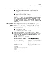
Switch-over to the redundant module occurs in the following situations:
Malfunction of the active switching module.
Manual reboot of the CoreBuilder 7000 by LMA, Telnet (soft reboot)
or Transcend NMS.
Software error in the active switching module.
Switch-over Reboot
Switching over from one module to another is not dependent on the
chassis configuration. Typical time is approximately 6-8 seconds. There is
no need to reboot the modules in the chassis and no software upload
occurs. Interruption of traffic on PVC connections is minimal
(200-300ms). SVC connections are automatically re-established within
7 seconds.
Communications
between Active and
Redundant Switches
A TFTP protocol is used for all communications between active and
redundant switches, whereby the redundant switch acts as the TFTP
server and the active switch acts as the TFTP client. The active switch
performs a TFTP upload of all needed information: flash regions, memory
databases and software, which are treated as prioritized “files”. Flash
regions and databases are sent whenever they are changed and software
can only be sent following a manual LMA or NMS request.
The active and redundant switches can send special ICP messages from
one to another only via an interface card inserted in the CoreBuilder
7000. 8-port, 4-port and 7200 are the preferred boards for inter-switch
communication.
Summary of Contents for CoreBuilder 7000
Page 12: ......
Page 30: ...30 CHAPTER 1 ATM NETWORK BASICS...
Page 32: ...32 CHAPTER 1 ATM NETWORK BASICS...
Page 34: ...34 CHAPTER 1 ATM NETWORK BASICS Figure 8 LANE Network over WAN...
Page 96: ...96 CHAPTER 4 PRIVATE NETWORK TO NETWORK INTERFACE PNNI VERSION 1 0...
Page 184: ...184 CHAPTER 7 LAN EMULATION VERSIONS 1 0 AND 2 0...
Page 206: ...206 CHAPTER 9 DEVICE MANAGEMENT...
Page 222: ...222 APPENDIX A TECHNICAL SUPPORT...
Page 234: ...234 APPENDIX B PROTOCOLS AND INTERFACES...
Page 238: ...238 APPENDIX C COREBUILDER 7000 FAMILY ATM SWITCH SPECIFICATIONS...
Page 242: ...242 APPENDIX D SAFETY INFORMATION...

