PNNI Routing
71
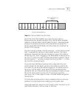
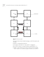
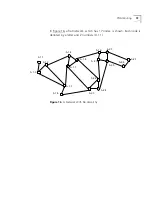
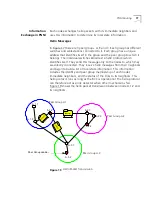
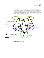
Switch D now has a decision to make. It does not know that Switch B
is connected to Switch A. Switch D can either send the signal to
Switch F or to Switch B.
Should it choose to send to F (as shown in number 3), then Switch F
will send the signal to E (as shown in number 4).
Switch E does not know that it is the source of the signal, so it sends
the signal to Switch C and the loop will continue until Switch D sends
to Switch B, or until the maximum hops are reached.
With PNNI, looping will not occur, because each node in the network
knows about all the other nodes in the network. See Chapter 13 in the
Management Guide for details on how to prepare the CoreBuilder 7000
for PNNI functions. Also see the
CoreBuilder
®
7000 Family ATM Switches
Installation & Setup Guide
for information on activating the PNNI option
during initial setup.
PNNI Routing
This section will cover the topological structures used in building a PNNI
network. The following topics are covered:
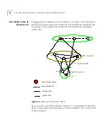
Organizing a Network Hierarchy
Information Exchange in PNNI
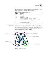
Uplinks in a Hierarchy
Organizing a
Network Hierarchy
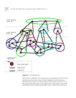
PNNI allows you to work in a hierarchical structure. Although this chapter
will explain how to create a hierarchy, is not necessary to build a hierarchy
in order to reap all the benefits of PNNI. A PNNI network is based on
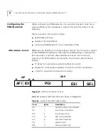
nodes. Each node is identified by its node ID. This ID is an ATM address
which identifies the node and the peer group to which it belongs. The
ATM address for the node is created when the switch is set up and
configured. See the
Installation & Setup Guide
for fast setup instructions.
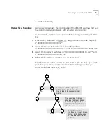
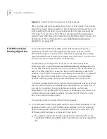
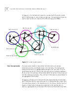
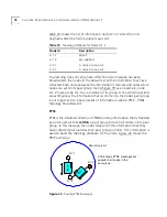
In order to create a hierarchical network, the network manager needs to
organize the network into groups. These groups can comprise a floor,
building, department or an entire campus. The network manager will also
have to make sure that the segmentation is scalable and will designate
which nodes will belong to which group. These groups are called
peer
groups
and are identified by the same peer group ID. This ID is defined as
a prefix of up to 13 bytes on an ATM End System Address, which is
assigned to the group by the network manager when the switch is set up.
Summary of Contents for CoreBuilder 7000
Page 12: ......
Page 30: ...30 CHAPTER 1 ATM NETWORK BASICS...
Page 32: ...32 CHAPTER 1 ATM NETWORK BASICS...
Page 34: ...34 CHAPTER 1 ATM NETWORK BASICS Figure 8 LANE Network over WAN...
Page 96: ...96 CHAPTER 4 PRIVATE NETWORK TO NETWORK INTERFACE PNNI VERSION 1 0...
Page 184: ...184 CHAPTER 7 LAN EMULATION VERSIONS 1 0 AND 2 0...
Page 206: ...206 CHAPTER 9 DEVICE MANAGEMENT...
Page 222: ...222 APPENDIX A TECHNICAL SUPPORT...
Page 234: ...234 APPENDIX B PROTOCOLS AND INTERFACES...
Page 238: ...238 APPENDIX C COREBUILDER 7000 FAMILY ATM SWITCH SPECIFICATIONS...
Page 242: ...242 APPENDIX D SAFETY INFORMATION...

