80
C
HAPTER
4: P
RIVATE
N
ETWORK
-
TO
-N
ETWORK
I
NTERFACE
(PNNI) V
ERSION
1.0
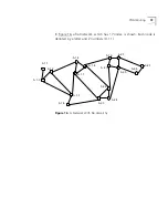
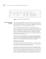
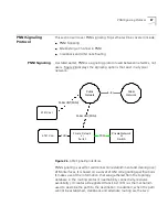
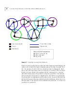
Figure 21
Partial Topology Database Readout
Peer Group Leader
Elections
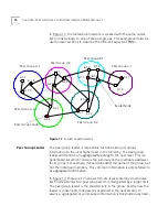
After the topology databases of each peer group are synchronized, the
nodes ask each other for their priority level. The network manager assigns
a priority level to each node as it is configured. The default is 0. Any node
assigned a higher number is considered to have priority.
Peer Group Leader Elections
(PGLE) are held periodically. When the
election is held, each node looks at its priority level and also looks at the
levels of all nodes within its group. Each node fills in a “ballot” with the
name of the peer group it considers to have the highest priority. When
there is one node that has a 66% majority, it is “elected” as the peer
group leader. In peer group A.1, node A.1.2 has the highest priority and
is chosen as the peer group leader.
For information on how to designate a peer group leader and parameters
via the LME, see "Get PGL Priority" on page 394 in the Management
Guide. Once the peer group leader has been elected, it raises its priority
by 50. This is to ensure that this node will remain as the leader.
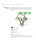
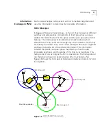
Moving up the Hierarchy
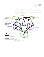
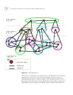
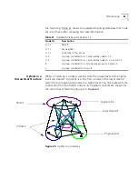
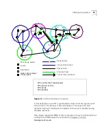
At this point, the peer group leaders of groups A.1, A.2 and A.3 meet in
the second level hierarchy. This level is a logical level, not a physical level.
The leaders also exchange Hello and PTSE protocols.
The groups that meet in this level of hierarchy are called
Logical Group
Nodes
, because they represent their entire group.This is where A.1 learns
about A.2 and A.3. The peer group leader for group A.1 will transmit to
its group all of the aggregated information it learned from groups A.2
and A.3. A new level called group A is created and A.2 is chosen as leader
for the group based on its priority level. A.2 will then go to the next
Node # 1 Id= A.1.2:60.0.0.0.0.3c.0.20.11.5.A.1.2
PTSE_Id Length Type Seq. no. CkSum Lifetime Description
1 68 97 1 95ae 35780 Nodal Inform.
4 92 288 1 39a7 35850 Horizont.Link
34 76 224 2 c05d 35790 Int.Reach.Addr
Summary of Contents for CoreBuilder 7000
Page 12: ......
Page 30: ...30 CHAPTER 1 ATM NETWORK BASICS...
Page 32: ...32 CHAPTER 1 ATM NETWORK BASICS...
Page 34: ...34 CHAPTER 1 ATM NETWORK BASICS Figure 8 LANE Network over WAN...
Page 96: ...96 CHAPTER 4 PRIVATE NETWORK TO NETWORK INTERFACE PNNI VERSION 1 0...
Page 184: ...184 CHAPTER 7 LAN EMULATION VERSIONS 1 0 AND 2 0...
Page 206: ...206 CHAPTER 9 DEVICE MANAGEMENT...
Page 222: ...222 APPENDIX A TECHNICAL SUPPORT...
Page 234: ...234 APPENDIX B PROTOCOLS AND INTERFACES...
Page 238: ...238 APPENDIX C COREBUILDER 7000 FAMILY ATM SWITCH SPECIFICATIONS...
Page 242: ...242 APPENDIX D SAFETY INFORMATION...


