Planning a Network with E-IISP
59
LANE redundancy
Hierarchical Topology
As discussed previously, the routing algorithm of E-IISP assumes that you
have constructed your network with a hierarchical topology.
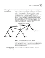
As an example, create a hierarchical switch topology consisting of three
trees.
1
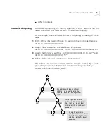
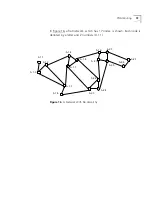
In the A tree, illustrated in Figure 13, assign to the root node the prefix
47.00.00.00.00.00.00.00.00.A*.
2
Assign the two switches one level lower the prefixes
47.00.00.00.00.00.00.00.00.A2* and 47.00.00.00.00.00.00.00.00.A5*.
3
Assign the third-level switches 47.00.00.00.00.00.00.00.00.A2.7* and
47.00.00.00.00.00.00.00.00.A1.53*.
4
Define the fourth-level switches in a similar manner.
This defines a tree whose common element is A (the ‘A’ tree). By a similar
procedure you create a ‘B’ tree and a ‘C’ tree making sure that you
connect the three roots A, B, and C.
An address with two significant
nibbles is one level lower in the
tree hierarchy than one significant
nibble.
Three significant nibbles
indicate a third level address.
Note that the higher-order
nibbles are the second-level
address.
X significant nibbles
indicate an X level address.
Note that the higher-order
nibbles are the X-1 level
address.
A
A5
A2
A53
A531
A536
A27
Summary of Contents for CoreBuilder 7000
Page 12: ......
Page 30: ...30 CHAPTER 1 ATM NETWORK BASICS...
Page 32: ...32 CHAPTER 1 ATM NETWORK BASICS...
Page 34: ...34 CHAPTER 1 ATM NETWORK BASICS Figure 8 LANE Network over WAN...
Page 96: ...96 CHAPTER 4 PRIVATE NETWORK TO NETWORK INTERFACE PNNI VERSION 1 0...
Page 184: ...184 CHAPTER 7 LAN EMULATION VERSIONS 1 0 AND 2 0...
Page 206: ...206 CHAPTER 9 DEVICE MANAGEMENT...
Page 222: ...222 APPENDIX A TECHNICAL SUPPORT...
Page 234: ...234 APPENDIX B PROTOCOLS AND INTERFACES...
Page 238: ...238 APPENDIX C COREBUILDER 7000 FAMILY ATM SWITCH SPECIFICATIONS...
Page 242: ...242 APPENDIX D SAFETY INFORMATION...

