58 / 218
2. Check the spark plug
a. Check whether the insulator is cracked or damaged,
whether the center electrode is abraded, fouled, corroded,
excessively carbonized or discolored (the color of the ceramic
insulator around the middle electrode of the spark plug
should be light brown). If so, replace the spark plug with a
new one.
b. Clean the electrode with a special spark plug cleaner.
Use a hard iron wire or steel needle to remove the attached
carbon deposits.
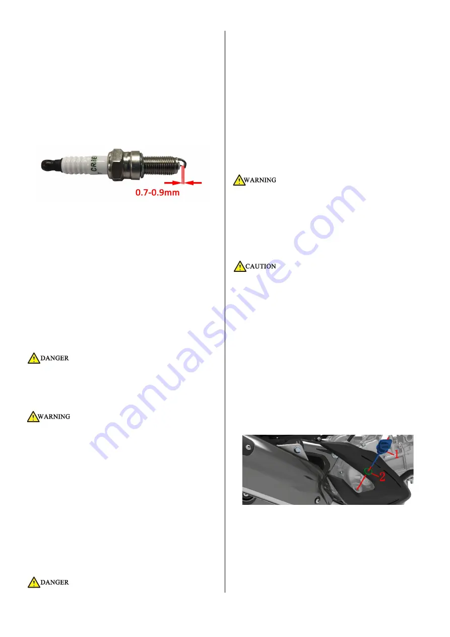
c. Use a feeler gauge to inspect the gap between the
center electrode and the side electrode.
d. If necessary, the gap can be adjusted by bending the
side electrodes, paying attention to the strength during
adjustment.
e. Clean the surface of the spark plug gasket and the joint
surface, and wipe off the dirt on the thread.
f. First screw it back to the engine by hand, and then use
the tool to turn it clockwise to the standard torque.
Model: NGK CR8EI-8
Resistance between the terminal screw and the center
electrode: 3
~
7.5kΩ
Clearance: 0.7-0.9mm (0.028-0.035in)
Torque: 14N.m (1.4kgf.m, 10 lbf.ft)
3. Refer to the steps to remove the spark plug to
restore all parts.
●The vehicle must be parked on a flat and stable ground or a
lifting platform.
●The operation can only be performed after the engine has
cooled down completely.
●Do not pull or knock the center electrode.
●If the replacement of inappropriate heating value or inferior
spark plugs causes engine damage, it is not within the scope
of the three guarantees.
●When installing the spark plug, the torque should not be
too large, and the thread should be screwed in manually
before tightening. If there is no torque wrench to replace the
spark plug, you can turn it by hand until there is resistance
and then rotate it 1/2 turn. For example, if you use an old
spark plug, you can turn it to the standard torque as soon as
possible.
●Pay attention and order when removing the plastic buckle
to avoid the buckle from breaking.
Engine oil
●The veh
icle must be parked on a flat and stable ground or a
lifting platform.
●Once the engine and muffler have cooled down, the
operation can be performed.
●When adding engine oil, prevent the engine oil from
dripping onto the surface of the muffler.
●The engine
oil should be kept away from children and pets.
Short-term contact with engine oil may irritate the skin.
Please wear long-sleeved clothes or sleeves and anti-shake
gloves before changing the oil. If you accidentally get oil, you
need to clean it thoroughly with soapy water.
●Replaced waste engine oil must be collected uniformly and
handed over to professional organizations for proper
disposal. It is forbidden to dump at will, into trash cans or
directly onto the ground, etc.
●The engine oil and gear box oil should be replac
ed
according to the periodic table specified in the manual.
●It is necessary to purchase regular and qualified engine oil.
Inferior engine oil will aggravate engine wear and, in severe
cases, will cause engine failure and shorten service life.
●The amount
of oil should meet the requirements, too much
or too little may cause engine damage.
●The copper gasket and the combination gasket need to be
replaced after disassembly; the O-ring and gasket are
recommended to be replaced with new ones.
●O
-rings need to be assembled in place to avoid trimming.
●After removing the oil dipstick and the filler nut, it is
necessary to prevent foreign matter from falling into the
engine.
M310
1. Drain the oil
a. Start the vehicle and turn off the engine for 3-5 minutes
after idling for 3-5 minutes.
b. Use the main bracket to park the vehicle firmly.
c. Rotate the oil dipstick
⑴
on the right side of the engine
counterclockwise, and remove the oil dipstick
⑴
and O ring
⑵
to accelerate the oil flow.
d. After placing an oil pan under the oil drain bolt, use a
14# sleeve to remove the oil drain bolt
⑶
and the combined
seal gasket
⑷
.
Содержание ZT125-M 2022
Страница 1: ...1 218 ZT125 310 350T M Maintenance Manual 2022 11 25...
Страница 111: ...111 218 l So far the adjustment operation of the valve clearance is completed...
Страница 138: ...138 218 Electrical schematic diagram of EFI system...
Страница 182: ...182 218 Exploded view of front fork components M125 310 Directional exploded view...
Страница 183: ...183 218 M350 Directional exploded view...
Страница 184: ...184 218 Front fork exploded view M125 310 The M125 are similar to the M310 taking the M310 as an example...
Страница 185: ...185 218 M350...
Страница 186: ...186 218 Exploded view of lower link board M125 310 The M125 are similar to the M310 taking the M310 as an example...
Страница 187: ...187 218 M350...
Страница 198: ...198 218 difference is that the M350 has one less adjusting nut and one more step to remove the connecting plate...


