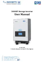
ZCS Azzurro 3000SP Скачать руководство пользователя страница 1


Ident

ific

az

ione:

 M

D

-AL

-GI

-00


R

ev

. 4

.0

 del

 31

.0

1.1

- A

ppl

ic

az

ione

G

ID


Reg. Pile  IT12110P00002965 - 

Capitale Sociale € 100.000,00 I.V. 

Reg. Impr. AR n.03225010481 - REA AR - 94189 
Azienda Certificata  ISO 9001 - Certificato  n. 9151 - CNS0 - IT-17778 


Zucchetti Centro Sistemi S.p.A. - Green Innovation Division 
Via Lungarno, 248 - 52028 Terranuova Bracciolini - Arezzo, Italy  
tel. +39 055 91971 - fax. +39 055 9197515 
[email protected] - [email protected] 

– 

www.zcsazzurro.com


3000SP Storage inverter 

User Manual 


11-06-2019 

V1.8 (For firmware version V1.90 or higher) 


Содержание Azzurro 3000SP

Страница 1: ...89 Azienda Certificata ISO 9001 Certificato n 9151 CNS0 IT 17778 Zucchetti Centro Sistemi S p A Green Innovation Division Via Lungarno 248 52028 Terranuova Bracciolini Arezzo Italy tel 39 055 91971 fax 39 055 9197515 innovation zcscompany com zcs pec it www zcsazzurro com 3000SP Storage inverter User Manual 11 06 2019 V1 8 For firmware version V1 90 or higher ...

Страница 2: ...t overview 10 3 2 Packing List 11 3 3 Installation environment 12 3 4 Installation tools 12 3 5 Wall installation position 13 3 6 Mounting instructions 14 4 Electrical connections 16 4 1 Battery connections 17 4 2 CT RS485 NTC Connections 17 4 3 Grid Connections 20 4 4 Critical Load Connection EPS function 21 5 Indicator lights and buttons 23 5 1 Buttons 23 5 2 Indicator lights 23 5 3 Operating St...

Страница 3: ...storage inverter 6 4 3 System information 45 6 4 4 Software update 46 6 4 5 Energy statistics 48 7 Technical specifications 49 8 Troubleshooting and maintenance 51 Troubleshooting 51 8 1 Maintenance 55 9 Uninstalling 56 9 1 Steps for uninstalling the inverter 56 9 2 Packaging 56 9 3 Storage 56 9 4 Disposal 56 10 Warranty 57 ...

Страница 4: ...y the equipment even when it is transferred to another user or plant Copyright statement The copyright of this manual belongs to Zucchetti Centro Sistemi S p A No part of this manual may be copied including the software reproduced or distributed in any form or by any means without the permission of Zucchetti Centro Sistemi S p A All rights reserved ZCS reserves the right to final interpretation Th...

Страница 5: ...system Scope This manual describes the assembly installation electrical connection commissioning maintenance and troubleshooting of the ZCS 3000SP storage inverter Keep this manual so that it is accessible at all times Recipients This manual is intended for qualified technical personnel installers technicians electricians technical support personnel or anyone who is qualified and certified to oper...

Страница 6: ...d easy assistance and support The 3000SP storage system is the best solution to optimise the use of energy produced by renewable sources The system is able to manage the bidirectional flow of electricity while controlling the power produced by the photovoltaic modules the power stored and taken from the battery the power exchanged with the electrical grid and the power supplied to utilities The in...

Страница 7: ... or racks and make sure that the inverter is positioned vertically Choose a suitable location for the installation of the electrical equipment Make sure there is sufficient space for heat dispersion and to accommodate future maintenance Maintain adequate ventilation and ensure that there is enough air circulation for cooling If you have problems with the packaging that could damage the inverter or...

Страница 8: ...the polarity of the connections have not been reversed The switched off battery should be temporarily stored with the battery completely disconnected from the inverter and the loads in a cool dry and ventilated place Battery maintenance personnel must have the technical knowledge and skills to service the battery Batteries connected in parallel must be of the same model and have the same firmware ...

Страница 9: ... installing the inverter Residual voltage may be present on the inverter Before opening the inverter wait 5 minutes to ensure that the capacitors are completely discharged Be careful of high voltage Be careful of high temperatures Complies with the European Standards CE Grounding point Read this manual before installing the inverter Indication of the allowable temperature range Degree of protectio...

Страница 10: ...delivery Do not flip over shake or jerk the packaging during transport Before opening the box please check that the packaging of the product is intact and has not been damaged or tampered with Once the packaging has been opened please check the condition of the inverter and its accessories making sure that they have not been damaged during transport in particular carefully check the mechanical com...

Страница 11: ...er and mounting bracket 3 2 Contents of the packaging Carefully check the contents of the packaging before installation making sure that no element inside the packaging is missing or damaged The package should contain the following components 1 Storage inverter 1 mounting bracket 2 M5 screws 8 expansion plugs and screws 8 M6 flat washers 2 DC terminals 6 AC terminals 4 terminal caps ...

Страница 12: ...cs Dry clean and sheltered place Ambient temperature between 25 C and 60 C Relative humidity between 0 and 100 non condensing Presence of independent air intakes at the entrance and exit of the room No flammable or explosive materials in the vicinity Altitude below 2000 metres Connection to the electrical grid with over voltage category CATII and CATIII For further details on installation please c...

Страница 13: ... key To screw the inverter to the wall mounting bracket 5 Crimping tool To crimp the power cables 6 Multi meter To check the voltage and current values 7 Marker pen To mark the wall for better fixing precision 8 Measuring tape To measure distances 9 Level To make sure the bracket is level 10 ESD gloves Protective clothing 11 Safety goggles Protective clothing 12 Protection mask Protective clothing...

Страница 14: ...o sunlight or subject to the accumulation of snow so as to prevent damage to the internal components of the machine Figure 5 Correct installation of the 3000SP inverter 3 6 Assembly instructions 1 Correctly position the mounting bracket on the wall using a level to ensure that it is straight mark the eight holes using a suitable marker pen Drill the eight holes at the points marked on the wall usi...

Страница 15: ...inverter on the mounting bracket and secure it with the mounting bolt supplied 5 Secure the grounding connection of the 3000SP by means of the bolt supplied and using the appropriate hole in the heat sink 6 OPTIONAL Depending on the customer s requirements the 3000SP inverter can be locked to the mounting bracket with a safety lock not supplied with the kit Figure 7 Possibility of locking the inve...

Страница 16: ...verter during installation and maintenance a 100A DC disconnecting device must be installed between the 3000SP inverter and battery This operation is not necessary if lithium batteries with BMS are used as they have an internal disconnecting system such as Pylontech US2000B and US2000PLUS batteries supplied with the Azzurro ZCS storage inverter Note the Pylontech US2000B and US2000PLUS batteries a...

Страница 17: ...ections of a single phase system 4 1 Connecting the battery 1 Unscrew the 4 screws of the cover A with a star screwdriver figure 10 2 Remove the waterproof cover B loosen the cable gland C and then remove the stopper G 3 Route the battery cables F through the cable gland then connect them using the OT terminal E supplied the terminal must be screwed to the terminal block using the special star scr...

Страница 18: ...ntificazione MD AL GI 00 Rev 4 0 del 31 01 18 Applicazione GID Manual of 11 06 2019 Rev 1 8 User Manual for 3000SP storage inverter Figure 10 Connecting the power line of the battery 4 2 CT RS485 NTC connections ...

Страница 19: ...ving the meter The CTa will therefore measure the energy taken from and fed into the grid by the photovoltaic system The CTpv for measuring the photovoltaic production must be positioned on the phase cable exiting the photovoltaic inverter utility side or from the production counter and will only measure the energy generated by the photovoltaic inverter 2 Extend the cable of the two sensors with a...

Страница 20: ...f the cover connect the cable to the CT terminal supplied then insert the CT terminals into the corresponding ports CTa for the exchange sensor and CTpv for the production sensor 6 If using Pylontech batteries the communication cable between the inverter and batteries is supplied as an accessory inside the transparent bag in the inverter s packaging For Tawaki Maui and Weco ReSu4kWh batteries the ...

Страница 21: ...S Figure 15 Connecting the NTC cable 8 Replace the waterproof cover and secure it with the 4 screws tighten the cable gland 4 3 Connecting to the grid NOTE If you do not want to configure the EPS Emergency Power Supply option connect the AC power cable only to the GRID port and leave the LOAD port disconnected 1 Unscrew the 4 screws A of the right cover with a star screwdriver figure 15 2 Remove t...

Страница 22: ...ration and operation of the EPS mode in particular certain loads such as the electric motors of some pumps may require inrush currents much higher than those tolerated by the inverter causing a power failure The EPS function requires an AC power meter 2NC 2NA double switchover contactor to be installed in the system which is not included in the kit of the storage inverter and can be purchased sepa...

Страница 23: ... for connecting the GRID port shown in section 4 3 with the only difference being that the phase neutral and ground cables must be connected to the port marked LOAD For more information please consult the specific procedure available on the website www zcsazzurro com Figure 17 Diagram of the AC power contactor with 2NC 2NA double switchover Figure 18 Front and top view of the power contactor conne...

Страница 24: ...to the next number 5 2 Indicator lights 1 Indicator of the charge status Green o When the system is in charging control status the green LED flashes o When the system is charging the battery the green LED is steady o When the system is in alarm state temporary or permanent the green LED is off Indicator of the charging status Green o When the system is in discharging control status the green LED f...

Страница 25: ...r Manual for 3000SP storage inverter 5 3 Operating status Operating status Green discharging light Green charging light Red alarm light Discharging Steady Discharging control Intermittent Charging Steady Charging control Intermittent Standby Intermittent Intermittent EPS status Steady Steady Alarm Steady ...

Страница 26: ...een connected correctly 8 For lead acid batteries make sure that the NTC cable temperature probe has been connected correctly 6 2 Procedure for initial set up Important carefully follow the procedure below to start up the 3000SP inverter 1 Make sure that no power is generated by the photovoltaic system on the phase where the 3000SP inverter is connected open the DC circuit breaker between the inve...

Страница 27: ...d time 8 Min discharge voltage V 2 Country 9 Max discharge current A 3 Battery type 10 Min voltage threshold 4 Battery capacity 11 Discharge depth 5 Max charge threshold V 12 End of discharge V 6 Max charge current A 13 End of charge V 7 Overvoltage threshold Note settings 4 to 13 will only be present if the DEFAULT option has been selected 1 Date and time The date time format of the System is exp...

Страница 28: ...9 Reserved 10 China 22 General Europe 11 France 23 CEI 0 21 External 3 Battery type Use the Up and Down keys to select the type of batteries connected to the system and press OK to confirm If DARFON 1 PYLON 2 SOLTARO 3 ALPHA ESS 4 or General Lithium 5 batteries are used the setup of the 3000SP storage inverter will be completed press OK to enter into the main interface If other types of batteries ...

Страница 29: ...oltage V only for DEFAULT batteries Use the Up and Down keys to set the maximum charging voltage for the battery pack connected to the system check the battery datasheet press OK to move to the next value and confirm Once the setting has been completed the system will automatically move to the next section 6 Maximum charging current A only for DEFAULT batteries Use the Up and Down keys to set the ...

Страница 30: ...depth of discharge of the battery pack connected to the system check the battery datasheet press OK to move to the next value and confirm Once the setting has been completed the system will automatically move to the next section 12 End of Discharge voltage V only for DEFAULT batteries Use the Up and Down keys to set the end of discharge voltage for the battery pack connected to the system check th...

Страница 31: ...he batteries installed for one second the row of green LEDs underneath the word SOC will light up and then go off Repeat this for all the batteries connected in parallel 5 Close the DC circuit breaker if any positioned between the battery and 3000SP inverter 6 Close the AC circuit breaker between the 3000SP inverter and grid The display will light up and the 3000SP inverter will start operating 7 ...

Страница 32: ... battery pack If the power generated is less than the power consumed by the loads and the battery is not fully discharged the 3000SP will start to discharge the battery pack NOTE This start up procedure must be repeated each time the CT connection is changed 6 4 Menu From the main screen press the Menu Back button to enter the main menu The main menu contains five different options Main menu 1 Set...

Страница 33: ...press the Menu Back button and enter the password again After entering the password select the type of battery used in the system 1 Battery type Scroll up and down using the Up and Down keys to select the type of battery used Press OK to confirm the setting and wait for OK to appear on the display If you are using Pylontech lithium batteries supplied with the storage inverter select the option PYL...

Страница 34: ...of a power failure the 3000SP storage inverter will operate in EPS mode if this was previously set and will remain in discharge mode until the battery charge level drops to 20 4 Maximum charge current A Select 4 Maximum charge current A and press OK to enter the menu for setting the maximum charge current Press the Up and Down keys to change the value of the maximum charge current Press OK to move...

Страница 35: ...d press OK to enter the menu for setting the minimum discharge voltage Press the Up and Down keys to change the value of the minimum discharge voltage Press OK to move to the next digit and then confirm the setting wait for OK to appear on the display When setting this parameter for Pylontech batteries refer to the table in section 6 2 for different battery models refer to the relative datasheet 1...

Страница 36: ...l regulations Press the OK key and wait for OK to appear display For more information and to know the country regulations on board the inverter refer to the relevant section 5 Select communication address Select 5 Select Comm Address and press OK to enter the menu for selecting the communication address Press the Up and Down keys to change the first digit press OK to go to the next one and confirm...

Страница 37: ...PS Setting 1 Enable EPS Disable EPS 2 Set EPS start up time s Select the menu 1 EPS setting and press OK to enter use the Up and Down keys to select between Enable EPS and Disable EPS then press OK to confirm If the Enable EPS option is set select the menu 2 Set EPS start up time and press OK use the Up and Down keys to change the digit and OK to move to the next one When the AC voltage is interru...

Страница 38: ...untry code 01 or 15 has been set 11 Self Test 1 Fast Self test 2 STD Self test 3 Set PF time 3 Set QV time 5 Enable 81 S1 1 Fast self test Select 1 Fast Self Test then press OK to start the fast self test which will be performed automatically and will take about 15 minutes The following screens will be shown on the display Start Self test press OK to start Testing 59 S1 Wait Test 59 S1 OK Wait Tes...

Страница 39: ...Wait Testing 81 S2 Wait Test 81 S2 OK Wait Testing 81 S1 Wait Test 81 S1 OK Wait Testing 81 S2 Wait Test 81 S2 OK Press OK Self Test OK Press down 59 S1 253V 900ms Press down 59 S1 228V 902ms Press down 59 S2 264 5V 200ms Press down 59 S2 229V 204ms Press down 27 S1 195 5V 400ms Press down 27 S1 228V 408ms Press down 27 S2 92V 200ms Press down 27 S2 227V 205ms ...

Страница 40: ...f test with the difference that the waiting times are longer about 45 minutes due to the 300 second wait between one test and the next 3 Set PF time Select 3 Set PF time and press OK to enter the menu for setting this parameter The display will show the following represents the time to be set in seconds Use the Up and Down keys to set the desired value Press OK and wait for OK to appear on the dis...

Страница 41: ...sed in seconds with which the change in Q power occurs 5 Enable 81 S1 Select 5 Enable 81 S1 and press OK Select 1 Enable 81 S1 or 2 Disable 81 S1 if you want to enable or disable this function Press OK and wait for OK to appear on the display This function enables the restrictive frequency thresholds required in some cases by local regulations 12 Working mode Select 12 Working Mode and press OK to...

Страница 42: ...y to charging the battery with the excess energy When the battery is fully charged or when the charging power is limited the excess energy will be exported to the grid When the energy from the photovoltaic system is once again lower than that requested by the loads the system will give priority to the energy stored in the battery When the sum of the energy produced by the photovoltaic system and s...

Страница 43: ... Indicates the charge percentage of the battery pack Battery cycles Indicates the number of complete charging and discharging cycles performed by the battery pack Battery Temp Indicates the temperature measured on the cells of the battery pack 2 Set Charge Mode Select 2 Set Charge Mode and press OK to enter the menu for setting this Charge In this mode the user can select one or more time interval...

Страница 44: ...t to charge the batteries Outside the charging period the inverter returns to automatic mode The option to set the day of the week and months of the year allows greater flexibility in the management of the charging procedure For example setting it only on weekends when consumption is higher or in the winter months when the inverter produces less power It is also possible to set multiple rules or t...

Страница 45: ...e the SD card has been inserted back into its slot press Up or Down to select from the menu in question 1 Set Start Param 2 Set safety V 3 Set safety Hz Press OK and wait for OK to appear on the display Note for more information and to request the firmware update files please contact Azzurro ZCS Technical Support on the toll free number 800 727464 or at the email address service interver zcscompan...

Страница 46: ...formation on the inverter and batteries Scroll with the Up and Down keys to view all the screens An example of the screen is shown in the table below Note the number and type of information may vary depending on the type of battery set System Info System info 1 Serial number Serial number of the machine Software version Software version installed Hardware version Hardware version RS485 address Add...

Страница 47: ...firmware Proceed as follows 1 Switch off the ZCS 3000SP inverter by disconnecting the AC power and turning off the batteries If Pylontech batteries are used set the switches of each battery in the pack to 0 If Weco ReSU 4K4 batteries are used press the power button for 5 seconds until the RUN light turns off If Tawaki Maui 4 kWh batteries are used press the POWER button so that it is OFF making su...

Страница 48: ...rocess will take about 3 minutes and will run automatically 12 Check that the inverter completes the update correctly and that it is in the final FAULT condition normal since the inverter is disconnected from the AC grid If the message Communication Failed appears switch off the inverter and repeat the procedure starting from step 7 13 Once the update has been successfully completed the country mu...

Страница 49: ...nformation and to request the firmware update files please contact the Azzurro ZCS Technical Support via the toll free number 800 727464 or at the email address service interver zcscompany com 6 4 5 Energy Statistics To enter the screen containing the energy statistics of the system go back to the main interface and press the Menu Back key scroll down with the arrow to point 5 Energy Statistics an...

Страница 50: ...ency range 44 55Hz 54 66Hz according to the local standards Total harmonic distortion 3 Power factor 1 default Adjustable 0 8 EPS Output Emergency Power Supply Power supplied in EPS mode 3000 VA EPS output voltage and frequency 230 V 50Hz 60Hz Current supplied in EPS mode 13 A Total harmonic distortion 3 Switch time 3 s default adjustable from 1 to 999 s Efficiency Maximum charge efficiency 94 1 M...

Страница 51: ... Manual for 3000SP storage inverter Environmental protection rating inverter IP65 Allowable relative humidity range 0 95 Without condensation Maximum operating altitude 2000m Noise level 25db 1m Weight 16kg Cooling Natural convection Dimensions HxWxD 532 x 360 x 173mm Display LCD display Warranty 10 years ...

Страница 52: ...rms and errors Error code Error name Error description Possible solution ID01 GridOVP Grid voltage is too high If these errors occur occasionally the cause may be that the grid voltage is outside the standard parameters The 3000SP inverter will automatically return to normal operation when the grid is within the normal range again If the alarms are frequent it is recommended to measure the voltage...

Страница 53: ... Hardware protection trip ID17 HwADFaul tIGrid Sampling error of the grid current ID18 HwADFaul tDCI DCI sampling error ID19 HwADFaul tVGrid Sampling error of the grid voltage ID21 MChip_Fau lt Microprocessor fault ID22 HwAuxPo werFault Error on the auxiliary supply voltage ID25 LLCBusOV P Voltage on LLC line is too high ID26 SwBusOVP Voltage on the communication line is too high Software protecti...

Страница 54: ...erter and batteries Check that the ventilation conditions of the device are ideal Otherwise set lower charge and discharge current values In case of continuous and persistent error contact Technical Support ID58 OverTemp Fault_Heat Sin k Inverter heat sink temperature is too high ID59 OverTemp Fault_Env Ambient temperature is too high ID65 Unrecover HwAcOCP Grid current is too high Unrecoverable h...

Страница 55: ...nstalled is not suitable for the type of inverter Contact Technical Support ID95 CommEEP ROMFault EEPROM of the communication board cannot be read ID95 ID96 are internal errors of 3000SP Switch off the unit by disconnecting the AC and DC switches and wait for at least 5 minutes Switch the unit back on again by closing the AC and DC switches and check if the error is still present If so contact Tec...

Страница 56: ...t ID107 BatUTC Under temperature protection of battery charge 8 2 Maintenance Inverters generally do not require daily or routine maintenance In any case for proper long term operation of the inverter make sure that the heatsink for cooling the inverter has enough space to ensure adequate ventilation and that it is not obstructed by dust or other items Cleaning the inverter Use an air compressor a...

Страница 57: ...tors from the inverter Remove the connectors for communication with the batteries current sensors and NTC temperature probe Remove the AC terminals Unscrew the fixing bolt of the bracket and remove the inverter from the wall 9 2 Packaging If possible pack the inverter in its original packaging 9 3 Storage Store the inverter in a dry place where the ambient temperature is between 25 and 60 C 9 4 Di...

Страница 58: ...of the inverter If the inverter is defective or faulty during the warranty period contact your installer or supplier If the fault falls within the responsibility of the manufacturer Zucchetti Centro Sistemi S p A will provide service and maintenance free of charge Warranty exclusions Use of the 3000SP storage inverter for any other purpose than the intended one Defective or faulty design or instal...

Отзывы: