10.1 Alarm Displays
10-13
10
Trou
blesh
ooting
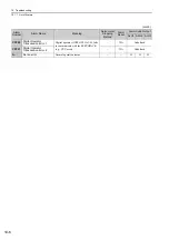
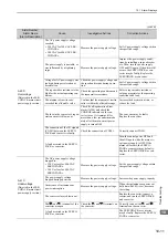
A.520:
Vibration Alarm
Abnormal vibration was detected
at the motor speed.
Check for abnormal noise from the
servomotor, and check the speed
and torque waveforms during oper-
ation.
Reduce the motor speed or reduce
the speed loop gain (Pn100).
The moment of inertia ratio
(Pn103) value is greater than the
actual value or is greatly
changed.
Check the moment of inertia ratio.
Set the moment of inertia ratio
(Pn103) to an appropriate value.
A.521:
Autotuning Alarm
(Vibration was detected
while executing the one-
parameter tuning, Easy-
FFT, or tuning-less func-
tion.)
The servomotor vibrated consid-
erably while performing tuning-
less function.
Check the motor speed waveform.
Reduce the load so that the moment
of inertia ratio falls within the
allowable value, or raise the load
level using the tuning-less levels
setting (Fn200) or reduce the rigid-
ity level.
The servomotor vibrated consid-
erably during one-parameter tun-
ing or EasyFFT.
Check the motor speed waveform.
Check the operation procedure of
corresponding function and take a
corrective action.
A.710:
A.720:
Overload
A.710: High Load
A.720: Low Load
Incorrect wiring or contact fault
of servomotor and encoder.
Check the wiring.
Confirm that the servomotor and
encoder are correctly wired.
Operation beyond the overload
protection characteristics.
Check the servomotor overload
characteristics and executed run
command.
Reconsider the load conditions and
operating conditions. Or, increase
the motor capacity.
Excessive load was applied dur-
ing operation because the servo-
motor was not driven due to
mechanical problems.
Check the executed operation refer-
ence and motor speed.
Remove the mechanical problems.
A fault occurred in the SERVO-
PACK or converter.
−
The SERVOPACK or converter
may be faulty. Replace the SERVO-
PACK or converter.
A.730:
A.731:
Dynamic Brake
Overload
(An excessive power
consumption of dynamic
brake was detected.)
The servomotor rotates because
of external force.
Check the operation status.
Take measures to ensure the servo-
motor will not rotate because of
external force.
The rotating energy at a DB stop
exceeds the DB resistance capac-
ity.
Check the power consumed by DB
resistance (Un00B) to see how
many times the DB has been used.
Reconsider the following:
• Reduce the motor reference
speed.
• Reduce the moment of inertia
ratio.
• Reduce the number of times of
the DB stop operation.
The setting of Pn001.0 (Servo-
motor Power OFF or Alarm Gr.1
Stop Mode) is not correct.
Check the setting of Pn001.0.
To not use the dynamic brake, set
Pn001.0 to 2. (The dynamic brake
will not be used and the motor will
coast to a stop.)
The setting of Pn601 does not
agree with the dynamic brake
resistance that is connected.
Check the setting of Pn601.
Set Pn601 correctly.
The connection of the dynamic
brake unit is faulty.
Check the wiring between the
dynamic brake unit and DU, DV,
DW, and CN115 is correct and
securely connected.
Correctly wire and securely connect
the dynamic brake unit with DU,
DV, DW, and CN115.
A fault occurred in the SERVO-
PACK.
−
The SERVOPACK may be faulty.
Replace the SERVOPACK.
(cont’d)
Alarm Number:
Alarm Name
(Alarm Description)
Cause
Investigative Actions
Corrective Actions


