4.3 Trial Operation for Servomotor without Load from Host Reference
4-9
4
Tri
al Op
eration
4.3.4
Trial Operation in Position Control
Perform the following steps for trial operation in position control. The steps are specified on the condition that
input signal wiring for the position control has been completed according to
4.3.1 Inspecting Connection and Sta-
tus of Input Signals.
Step
Operation
Reference
1
Recheck the power supply and the input signal circuits, and turn ON the control
power supply of the SERVOPACK and converter.
3.3.4 Example of I/O Sig-
nal Connections in Posi-
tion Control
2
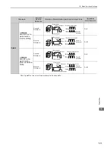
Set the reference pulse form with Pn200.0 according to the output pulse form of the
host pulse reference form.
5.4.1 Basic Settings for
Position Control
3
Set the reference unit, and then set the electronic gear ratio according to the host con-
troller. The electronic gear ratio is set in Pn20E and Pn210.
5.4.4 Electronic Gear
4
Turn ON the main circuit power supply of the SERVOPACK and converter.
−
5
Turn ON the servo ON (/S-ON) input signal.
−
6
Output a low-speed pulse reference for an easy-to-check number of rotations (e.g.,
one rotation) from the host controller.
−
7
Check the number of reference pulses input to the SERVOPACK from the changes in
the input reference pulse monitor before and after the reference.
The input reference pulse can be checked with Un00C.
−
8
Check the actual number of motor rotations from the changes in the feedback pulse
monitor before and after the reference.
The feedback pulse can be checked with Un00D.
−
9
Check that step 7 and step 8 satisfy the following formula.
Un00D = Un00C
×
(Pn20E/Pn210)
−
10
Check that the servomotor is rotating in the direction specified by the reference.
Note: To switch the motor rotation direction without changing the polarity of the
input pulse, refer to
5.2.2 Servomotor Rotation Direction.
5.2.2 Servomotor Rota-
tion Direction
11
Input a pulse reference for a comparatively large number of motor rotations from the
host controller so that the servomotor will rotate at a constant speed.
−
12
Check the reference pulse speed input to the SERVOPACK from the input reference pulse speed monitor (min
-1
).
The input reference pulse speed can be checked with Un007.
Note: Obtain Un007 from the following formula (if the model uses a 20-bit encoder)
.
13
Check the motor rotating speed (min
-1
). The motor rotating speed can be checked
with Un000.
−
14
Check that the values in step 12 and step 13 (Un007 and Un000) are equal to each
other.
−
15
Stop the pulse reference and turn OFF the servo ON signal (/S-ON).
−
Note: To ensure safety, set the reference pulse speed so that the motor speed will be
around 100 min
-1
.
Un007
input reference pulse speed
㨇
pulses/s
㨉
×
60
×
Pn210
Pn20E
1
2
=1048576
20
×
Reference input pulse speed
Electronic
gear ratio
Encoder
pulse


