ENGINE
6-38
3TNV88F Service Manual
Crankshaft and Camshaft Components
2. Measure bearing oil clearance prior to removing
the pistons and connecting rods to determine
extent of wear. Record the measurements.
NOTICE
Mark the connecting rod caps and connecting
rods so the caps and connecting rods stay
together.
1- Remove the bearing cap. Do not remove the
bearing inserts at this time.
2- Wipe oil from the bearing insert and
crankshaft journal surfaces.
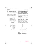
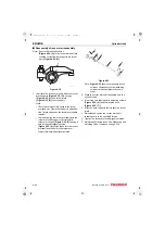
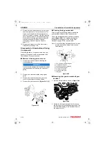
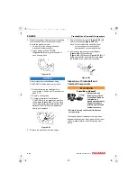
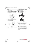
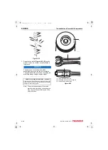
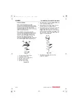
3- Place a piece of PLASTIGAGE
®
along the full width of the
bearing insert.
Figure 6-53
NOTICE
Do not rotate the crankshaft when using
PLASTIGAGE. A false reading may result.
4- Reinstall bearing cap and tighten to
specification.
5- Remove bearing cap.
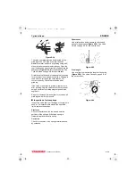
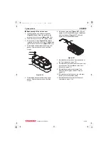
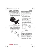
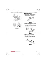
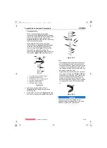
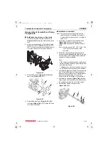
6- Compare the width of the flattened
PLASTIGAGE to the graduation marks on
the package
(Figure 6-54, (1))
. The mark
that most closely matches the width of the
flattened PLASTIGAGE will indicate the
bearing oil clearance.
Figure 6-54
7- Repeat with remaining connecting rods.
NOTICE
Do not allow the connecting rod to contact the
crankshaft journal during piston removal.
Damage to the bearing journal may result.
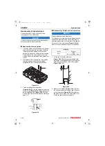
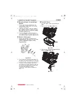
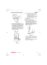
3. Use a wooden dowel against the connecting
rod and tap the piston/connecting rod assembly
out of the cylinder.
4. Mark the cylinder number on the piston and
connecting rod.
5. Remove the bearing inserts
.
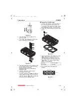
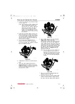
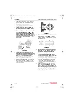
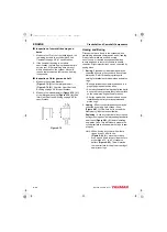
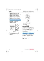
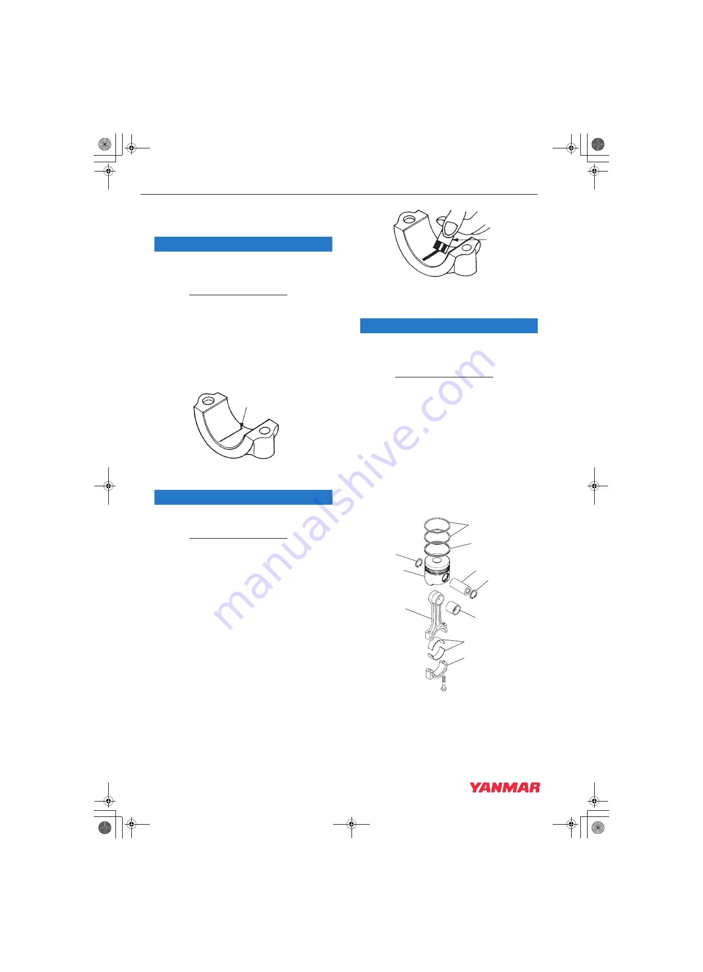
6. Remove the compression rings
(Figure 6-55, (3))
from the piston using a piston
ring expander.
7. Remove the oil ring
(Figure 6-55, (4))
from the
piston using a piston ring expander.
Figure 6-55
K0001898
1
K0001899
1
3
4
5
9
6
8
7
5
2
1
K0001960
3TNV88F_SVM_A4.book 38 ページ 2012年7月26日 木曜日 午後6時4分

