ENGINE
6-52
3TNV88F Service Manual
Crankshaft and Camshaft Components
Piston installation
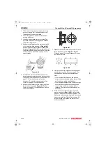
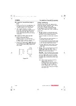
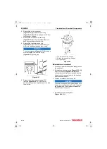
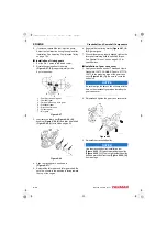
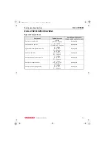
When correctly assembled, the piston
identification mark
(Figure 6-92, (2))
stamped
into the top of the piston will be on the same side
of the connecting rod as the match marks
stamped into the connecting
rod and connecting rod cap.
When installed in the cylinder, the piston
identification mark
(Figure 6-92, (2))
stamped
on the top of the piston must face the fuel
injection pump side
of the
engine and the embossed mark on the
connecting rod
must face the
(Figure 6-92, (5))
of the engine.
1 – Fuel injection pump side of engine
2 – Piston identification mark
3 – Embossed mark on connecting rod
4 – Rod and cap match marks
5 – Flywheel end of engine
6 – Camshaft side of engine
Figure 6-92
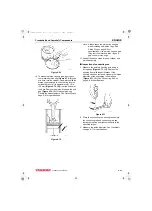
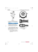
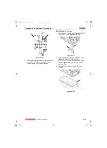
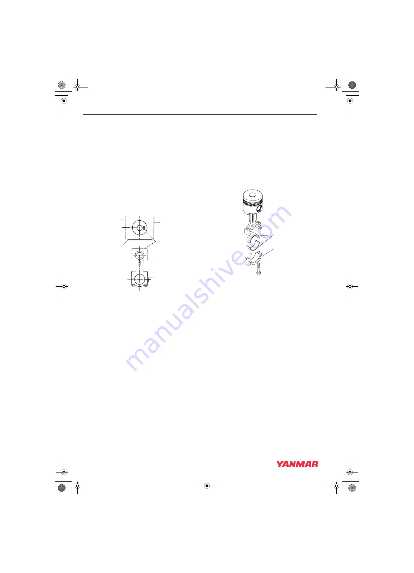
4. Reinstall the bearing inserts
(Figure 6-93, (1))
in the connecting rod and cap.
5. Apply a liberal coat of clean engine oil to the
bearing inserts and crankshaft journal.
6. Apply a light coat of clean engine oil to the rod
cap bolts. Reinstall the connecting rod cap
(Figure 6-93, (2))
. Tighten the connecting rod
bolts to the specified torque in two stages (1/2
then full torque).
page 6-10 for specifications.
Figure 6-93
7. Reinstall the remaining pistons in their
respective cylinders.
K0001967
1
6
5
3
2
4
K0001965
1
2
3TNV88F_SVM_A4.book 52 ページ 2012年7月26日 木曜日 午後6時4分

