ENGINE
6-48
3TNV88F Service Manual
Crankshaft and Camshaft Components
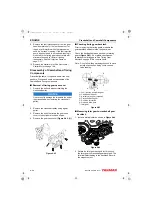
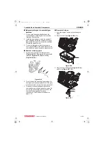
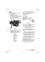
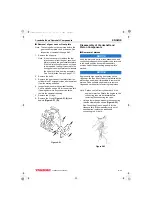
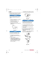
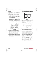
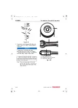
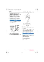
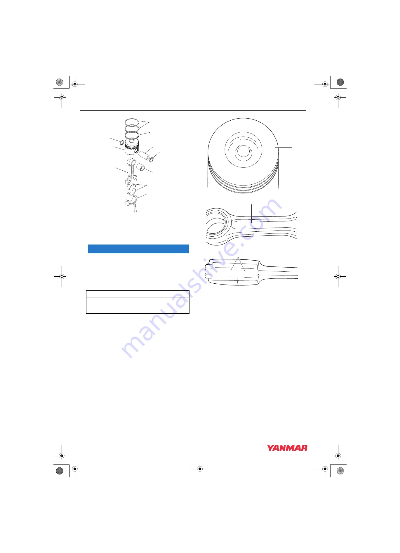
Figure 6-82
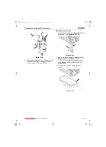
3. Reinstall one circlip
(Figure 6-82, (5))
into the
piston. Ensure the circlip is securely seated in
the groove.
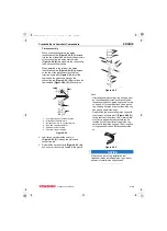
NOTICE
The piston and connecting rod must be
assembled together in the correct orientation.
The orientation of the piston and connecting rod
are different depending on engine model.
Note: The actual appearance of the match
marks on the piston and connecting rod
may vary, but they will always be in the
same locations.
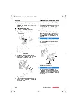
1 – Piston identification mark
2 – Embossed mark on connecting rod
3 – Rod and cap match marks
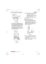
Figure 6-83
Piston to connecting rod orientation - by model
Orient the piston identification mark stamped on top of the
piston on the same side as the rod and cap match marks
stamped on the connecting rod.
3
4
5
9
6
8
7
5
2
1
K0001960
ML
V
88
1
046623-00X00
V84 R
2
046646-00X00
80 80
K0002089
3
3TNV88F_SVM_A4.book 48 ページ 2012年7月26日 木曜日 午後6時4分

