ENGINE
6-46
3TNV88F Service Manual
Crankshaft and Camshaft Components
■
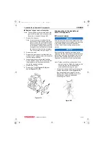
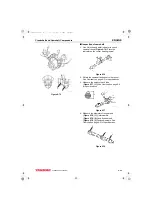
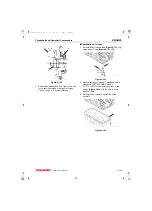
Inspection of camshaft bushing and
bores
1. Measure the I.D. of the front bushing and the
remaining bores in the cylinder block.
Camshaft on page 6-6 for specifications.
2. If the camshaft bushing is not within
specification, replace it using the appropriate
service tool. If the remaining bores are not
within specification, the cylinder block will
require replacement as there are no bearing
inserts used.
■
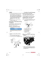
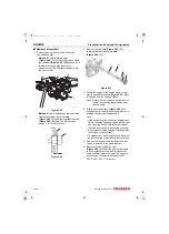
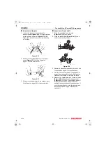
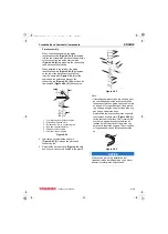
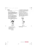
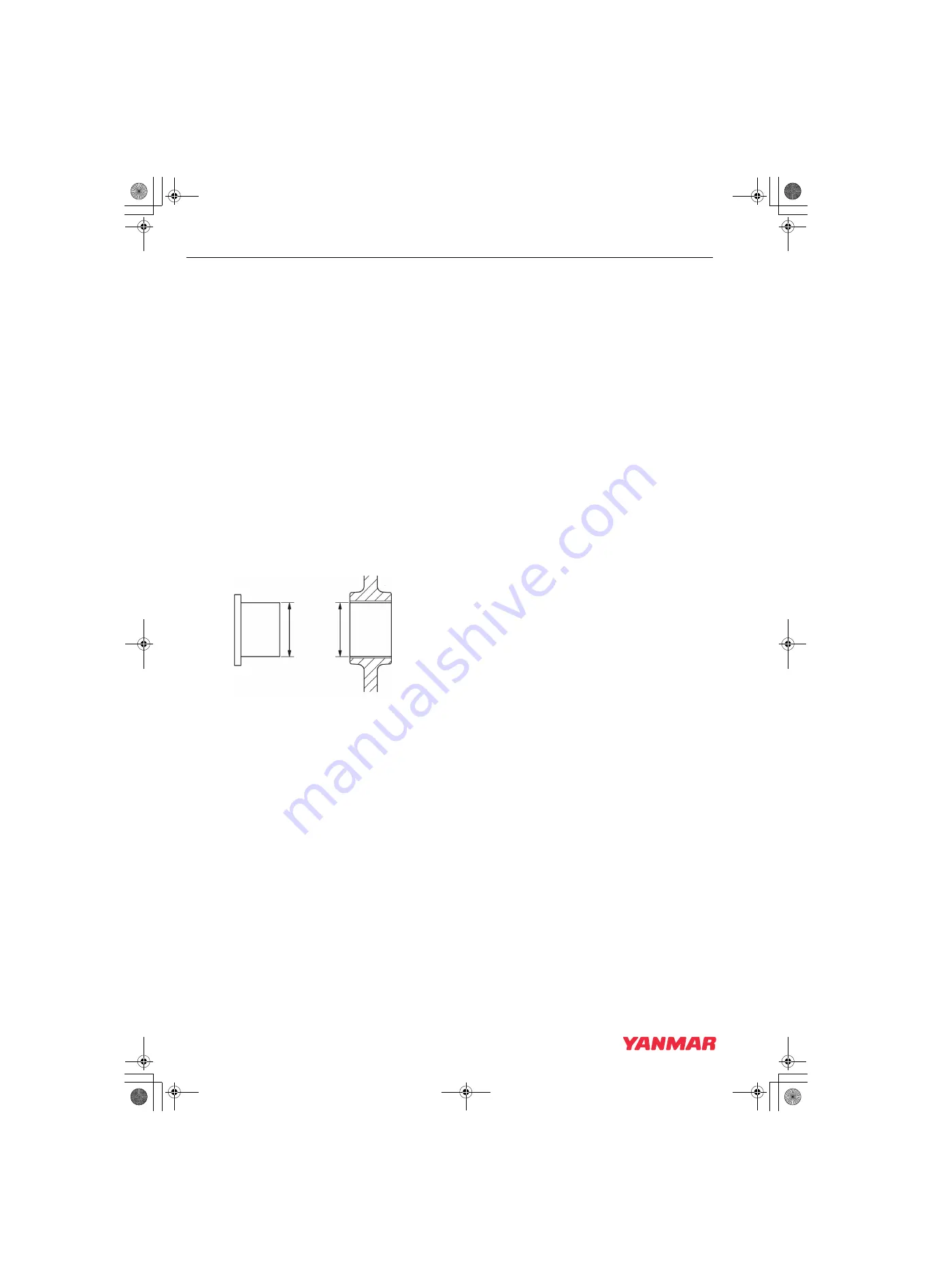
Inspection of idler gear and shaft
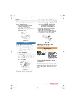
1. Measure the outside diameter
of the idler gear shaft
Bushing on page 6-6 for specifications.
2. Measure the inside diameter
(Figure 6-79, (3))
of the idler gear bushing
Idler Gear Shaft and Bushing on page 6-6 for
specifications.
Figure 6-79
Honing and Boring
Pistons must move freely in the cylinders while
maintaining adequate compression and oil sealing.
If the cylinder walls are scuffed, scored,
out-of-round, or tapered beyond specifications,
rebore and hone to restore cylinders to usable
condition. Slight imperfections can be corrected by
honing alone.
1.
Boring
- Significant cylinder damage may be
corrected by boring the cylinder to an oversize
dimension. Refer to the appropriate parts
catalog for available oversize pistons and piston
rings.
• Boring a cylinder should always be done in a
properly equipped machine shop.
• A bored cylinder should always be finished with
a hone to properly prepare the cylinder surface
so the new piston rings will seat properly.
• After the cylinder has been bored and honed,
install the appropriate oversize pistons and
piston rings.
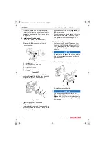
2.
Honing
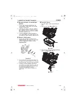
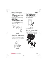
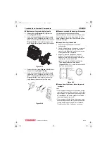
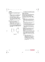
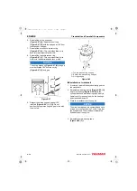
- Minor cylinder imperfections may be
corrected by using a rigid cylinder hone
(Figure 6-81, (1))
. Be sure not to exceed the
maximum cylinder bore specification.
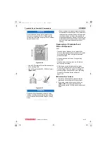
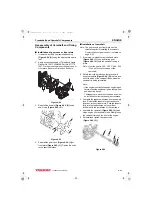
Deglazing
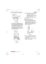
- A used cylinder that did not require
boring or honing, should always be deglazed with
a ball hone
before installing
new piston rings. This will properly prepare the
cylinder surface to allow new piston rings to seat
properly.
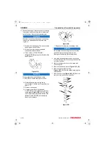
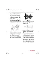
Note: When honing a cylinder, with either a
ridged hone or a ball hone
(Figure 6-80, (1)), move the rotating
hone up and down in the cylinder bore to
accomplish a 30° to 40° crosshatch
pattern (Figure 6-80). This will provide
the ideal surface for the proper seating of
new piston rings.
1
3
4
2
K0001714A
3TNV88F_SVM_A4.book 46 ページ 2012年7月26日 木曜日 午後6時4分

