ENGINE
6-50
3TNV88F Service Manual
Crankshaft and Camshaft Components
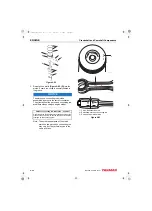
6. Reinstall the oil ring expander
. Reinstall the oil ring
with the end gap at 180° from
the expander end gap
.
7. Reinstall the second compression ring
This ring is identified by its
dark color and tapered face profile
.
8. Reinstall the top compression ring
. This ring is identified by its
silver color and barrel-shaped face profile.
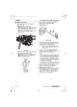
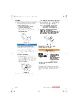
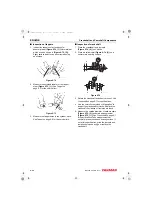
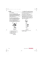
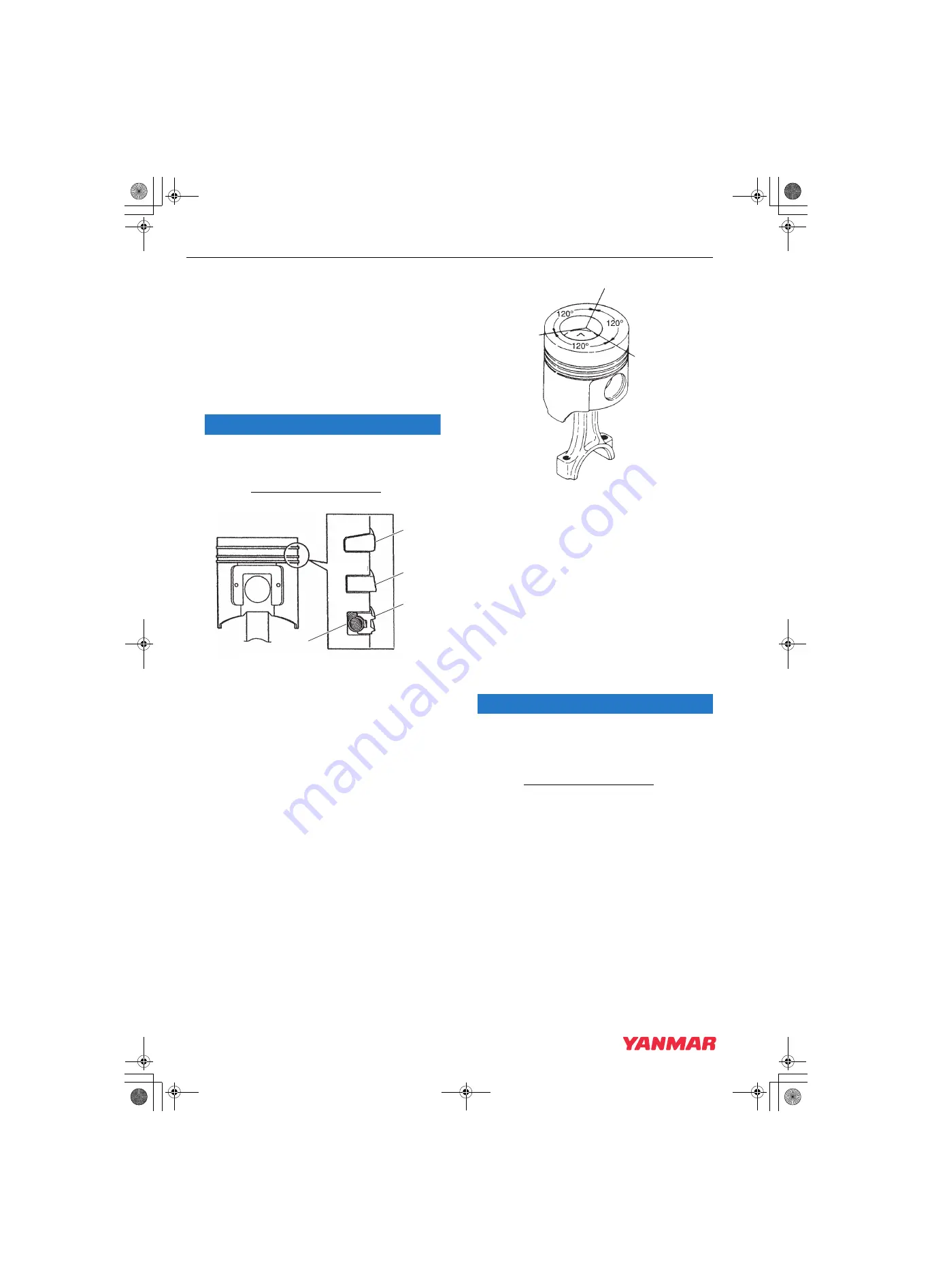
NOTICE
The oil ring expander
(Figure 6-87, (4))
end gap
must be located 180° from the oil ring
end gap.
Figure 6-87
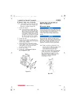
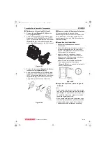
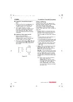
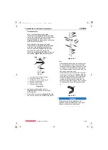
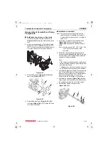
9. Stagger the piston ring end gaps at 120°
intervals
. Do not
position the top piston ring end gap in line with
the wrist pin.
1 – Top compression ring end gap
2 – Second compression ring end gap
3 – Oil ring end gap
Figure 6-88
■
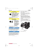
Installation of crankshaft
1. If removed, reinstall the keys and timing gear on
the crankshaft.
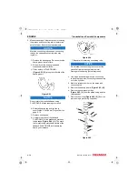
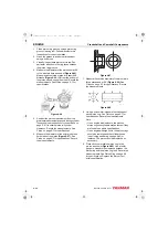
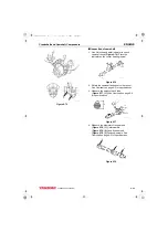
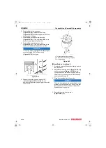
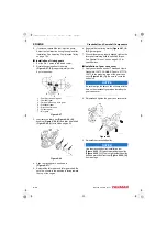
2. Reinstall new bearing inserts
and thrust bearing
(Figure 6-89, (2))
in the
cylinder block and main bearing caps. Apply a
liberal coat of clean engine oil to the bearings
and crankshaft journals.
3. Place the crankshaft into the engine.
NOTICE
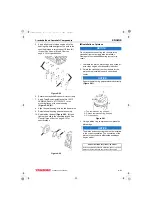
The main bearing caps are numbered and have
arrows for proper positioning. The No. 1 cap is at
the flywheel end. The arrows point toward the
flywheel end of the engine.
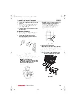
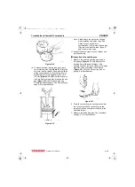
4. Reinstall the main bearing caps
(Figure 6-89, (3))
.
1
2
3
4
K0001722B
3
1
2
K0001968
3TNV88F_SVM_A4.book 50 ページ 2012年7月26日 木曜日 午後6時4分

