


FUEL SYSTEM
3TNV88F Service Manual
7-23
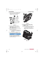
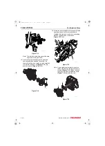
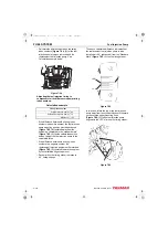
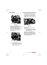
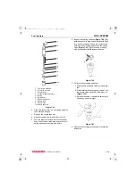
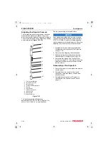
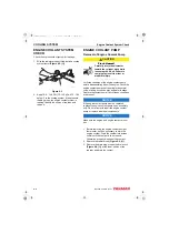
Checking and Adjusting Fuel Injection Timing
1 – 10° BTDC (Before Top Dead Center)
2 – 15° BTDC
3 – 20° BTDC
4 – Direction of rotation
5 – TDC (Top Dead Center)
Figure 7-38
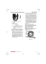
Note: The TDC (Top Dead Center) mark can
be identified by the cylinder numbers
stamped near the TDC mark on the
flywheel.
If you are uncertain as to the timing degree
designation of the timing marks on the flywheel
timing grid, you can determine the timing degree
designation by measuring the timing grid.
• First measure the distance between two of the
“longer” marks on the timing grid. (They are 5°
apart.) Then measure the distance from the
TDC mark to the first “longer” mark on the
timing grid. Divide that measurement by the
distance between the two “longer” marks. The
resulting answer will tell you how many
degrees there are between the TDC mark and
the first “longer” mark.
• EXAMPLE: If the distance between the two
“longer” marks is approximately 2.0 cm and the
distance from the TDC mark is approximately
4.0 cm, the answer is approximately 2. This
indicates there is 10° (2 × 5°) between the TDC
mark and the first “longer” mark on the timing
grid. That means the first “longer” mark on the
timing grid indicates 10° BTDC, the second
“longer” mark indicates 15° BTDC and the third
timing mark indicates 20° BTDC. If the answer
is 3, that indicates there is 15° (3 × 15°)
between the TDC mark and the first “longer”
mark and that the first “longer” mark indicates
15° BTDC with the second and third “longer”
marks indicating 20° BTDC and 25° BTDC
respectively.
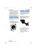
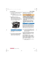
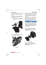
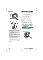
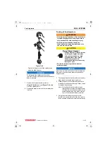
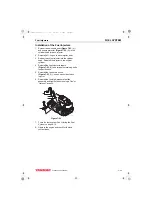
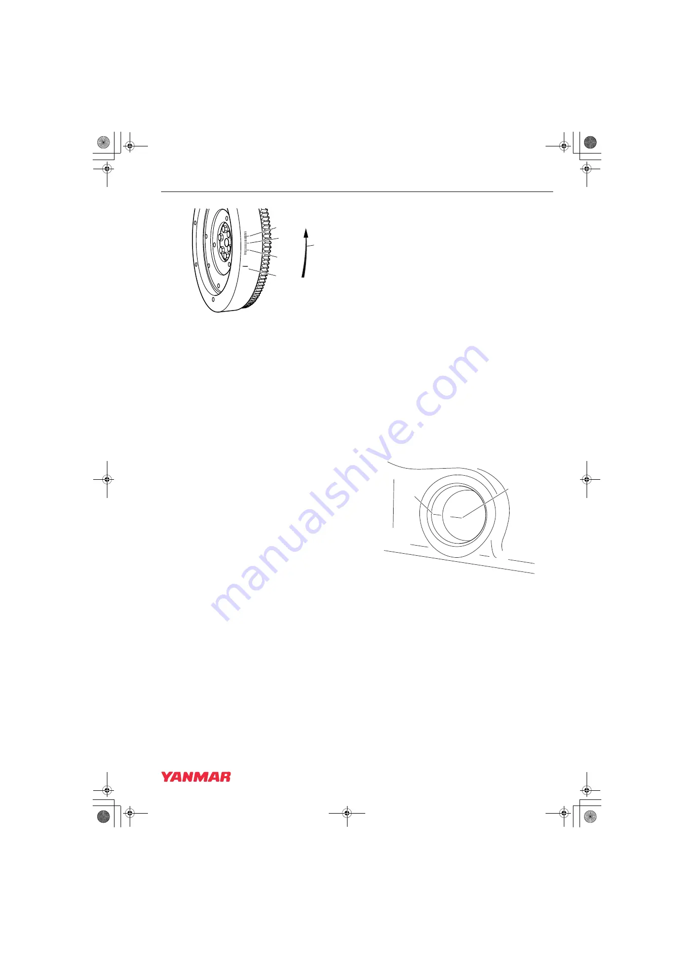
8. Highlight the timing reference mark
(Figure 7-39, (2))
on the flywheel housing or
. Highlight
the TDC (Top Dead Center) mark
(Figure 7-39, (1))
on the flywheel.
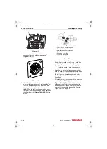
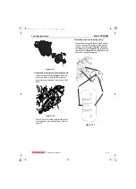
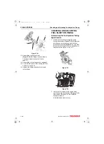
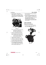
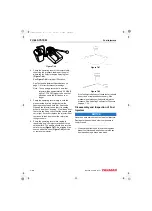
9. Highlight the target timing mark
(Figure 7-40, (1))
on the flywheel as calculated
in
Determining the Fuel Injection Timing
Figure 7-39
3
2
1
5
4
K0002071
1 4
1
4
K0002065
2
1
3TNV88F_SVM_A4.book 23 ページ 2012年7月26日 木曜日 午後6時4分