2 Instrument Configuration
Copyright © WOODLEY EQUIPMENT COMPANY LTD.
64
Installation
Follow the corresponding disassembly steps in reverse order.
⚫
Put on antistatic gloves and an electrostatic-shielding ring while operating to avoid damaging the
LED.
⚫
All the wirings need to be set up according to the original positions of the machine components
to prevent them from being crushed or otherwise damaged.
⚫
During transportation and installation, the flow chamber exposed at the bottom of the optical
system needs to be protected from being crushed or pressed. When pulling out the tubes, hold
the flow chamber by hand to prevent it from being dislocated by external force.
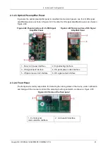
2.4.2 Replacing the Optical Preamplifier Panel
Purpose
The optical preamp panel can be disassembled and replaced by following the procedures specified
in this section; however, in each case,
Preliminary Steps
need to be taken before you begin.
Tools/Spare Parts
⚫
#2 (Ph2) Phillips screwdriver
⚫
New optical preamplifier panel
Preliminary Steps
1. Turn off the power switch on the left side of the device.
2. Pull out the power cord plug from the rear panel of the device.
3. Open the right-side door and disassemble the top cover panel.
4. Take down the cover panel of the optical system box.
Disassembly
1. Pull out the three wires from the optical preamp panel.
2. Use a #2 (Ph2) Phillips screwdriver to disassemble the four M3×8 cross-recessed pan-head
combination screws which affix the optical preamp panel, and carefully detach the cover panel of
the optical system box.
Содержание InSight V5
Страница 1: ...DMR MB 007 1 5...
Страница 126: ...7 Maintenance Inventory Copyright WOODLEY EQUIPMENT COMPANY LTD 120...
Страница 127: ...7 Maintenance Inventory Copyright WOODLEY EQUIPMENT COMPANY LTD 121...


